
Graphics Programming
Lecture 05 – Shaders
Edirlei Soares de Lima
<edirlei.lima@universidadeeuropeia.pt>
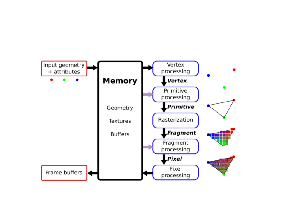
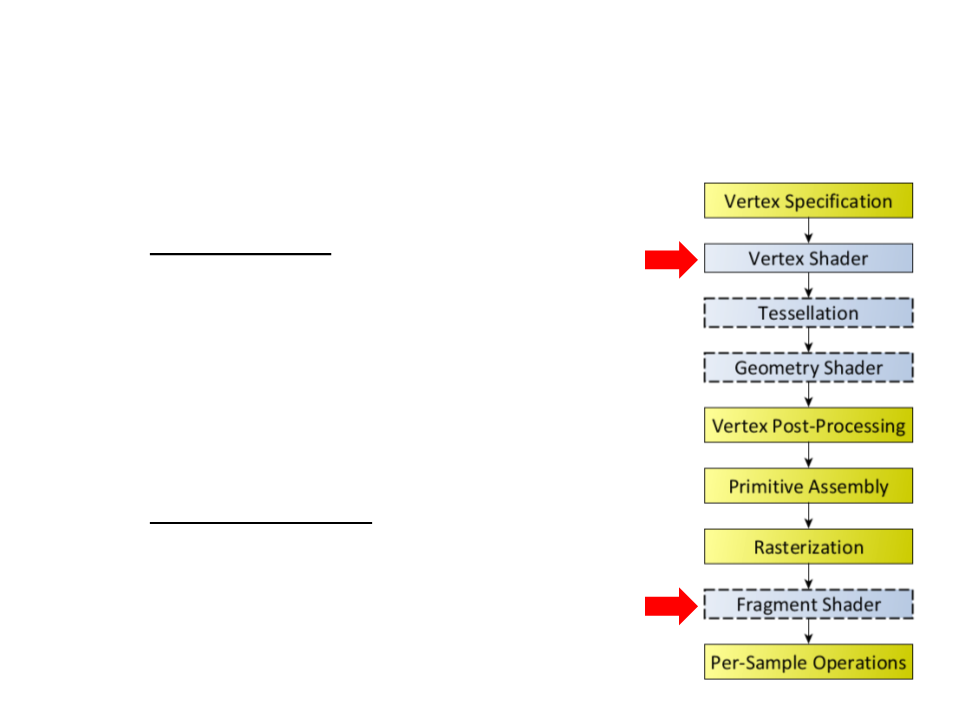
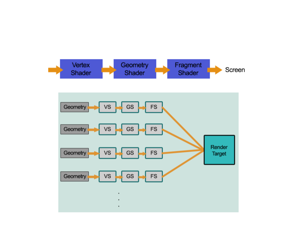
Graphics Pipeline

Shaders
•
•
Shaders are pieces of code written in a shading language.
They describe how to process data in the graphics pipeline.
The term “shader” was proposed by Cook [1984] to describe
small programs written by the user as part of the modeling
process to determine the color of objects.
•
Types of shaders:
–
–
–
–
Vertex shaders;
Fragment shaders;
Geometry shaders;
Tessellation shaders;

Shading Languages
•
•
•
GLSL – Standardized shading language used by OpenGL.
HLSL – C-style shader language for Direct3D.
Cg – Shading language developed by NVIDIA for easy and
efficient production pipeline integration.
•
•
RSL – Shader language used by the Pixar RenderMan software
(
offline rendering).
OSL – Shading language developed by Sony and also used in
Blender.
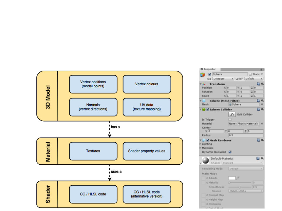
Shaders in Unity
•
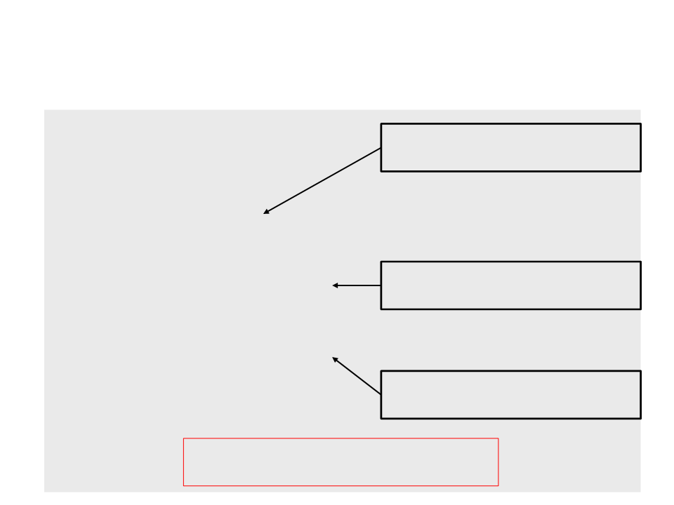
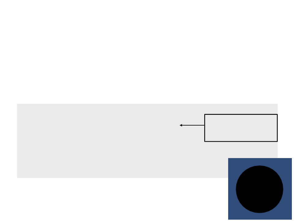
The rendering process in Unity is entirely based on shaders:
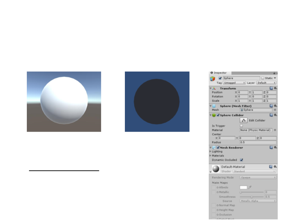
Shaders in Unity
•
The rendering process in Unity is entirely based on shaders:
with standard shader
without shader
•
Shading language: ShaderLab (HLSL + Cg).
Shaders in Unity
•
Main Unity Shader Types:
–
Unlit – Vertex, Frangment, Geometry, and Tessellation Shaders;
–
Surface – Code generation approach that makes it easier to write
lighting shaders;

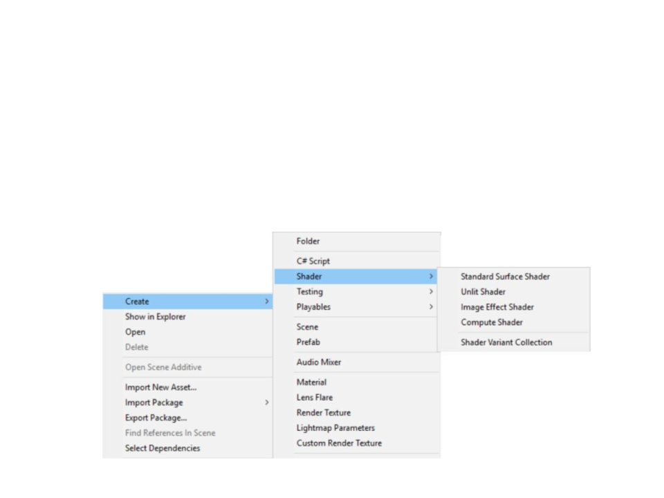
Shaders in Unity
•
Create a new shader: Create->Shaders->Unlit
Shader "Custom/MyShader"{
Properties{
}
SubShader{
Pass{
}
}
}
Vertex and Fragment Shaders
•
•
The Vertex Shader is responsible for
processing individual vertices of a mesh.
The Fragment Shader is responsible for
processing (usually coloring) the
fragments (generated by Rasterization)
that lie inside the mesh's triangles.
Vertex and Fragment Shaders
Shader "Custom/MyShader"{
Properties{
}
SubShader{
Pass{
Definition of the functions that will
be vertex and fragment programs.
CGPROGRAM
#
#
pragma vertex MyVertexProgram
pragma fragment MyFragmentProgram
Includes some essential
functionalities to write shaders.
#
include "UnityCG.cginc"
void MyVertexProgram(){
}
void MyFragmentProgram(){
}
ENDCG
Implementation of the vertex and
fragment programs/functions.
}
}
Note: this shader do not produce any
results (the objects using it will disappear).
}
Vertex and Fragment Shaders
•
To render something, the vertex program has to return the
final coordinates of an input vertex, which is sent to the
fragment program as input. The fragment program must
return the final color of the fragment.
float4 MyVertexProgram(float4 position : POSITION) : SV_POSITION
{
Transforms the vertex
from object space to
camera space.
return UnityObjectToClipPos(position);
}
float4 MyFragmentProgram(float4 position:SV_POSITION):SV_TARGET
{
return float4(0, 0, 0, 1);
}
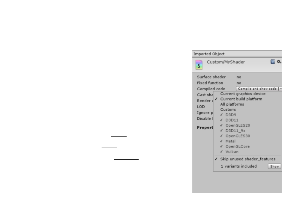
Unity Shader Compilation
•
•
Unity compiles the shader code to a
different shader language depending on
the target platform.
Different APIs and platforms require
different shader languages.
–
–
–
Windows – Direct3D: HLSL
MacOS – OpenGL: GLSL
Android – OpenGL ES: GLSL ES
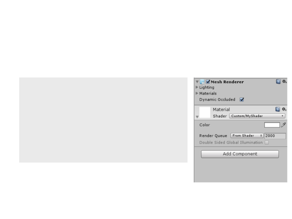
Shader Properties
•
Shader properties are declared in a separate block of code.
Shader "Custom/MyShader"{
Properties{
_
Color("Color", Color) = (1, 1, 1, 1)
SubShader{
..
}
.
}
}

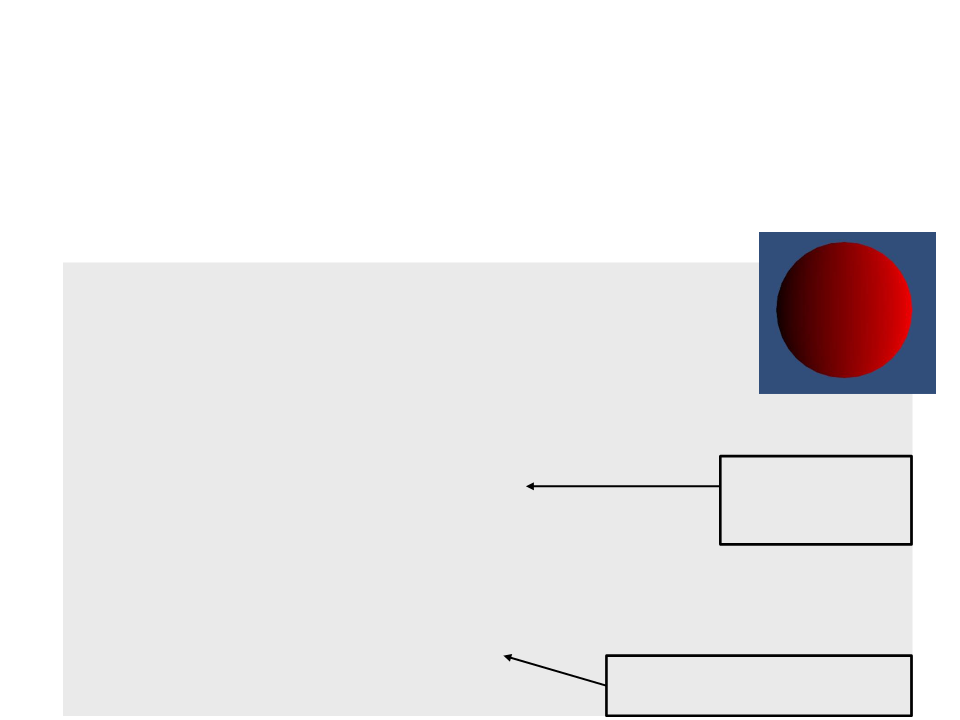
Shader Properties
•
Shader properties are declared in a separate block of code.
CGPROGRAM
.
..
float4 _Color;
float4 MyVertexProgram(float4 position:POSITION):SV_POSITION{
return UnityObjectToClipPos(position);
}
float4 MyFragmentProgram(float4 position:SV_POSITION):SV_TARGET{
return _Color;
}
ENDCG
Sending More Information From
Vertex To Fragment
We can define a structure to send more information about
each vertex to its respective fragment program.
•
.
..
struct VertexToFragment {
float4 position : SV_POSITION;
float3 localPosition : TEXCOORD0;
}
;
VertexToFragment MyVertexProgram(float4 position : POSITION){
VertexToFragment v2f;
v2f.localPosition = position.xyz;
v2f.position = UnityObjectToClipPos(position);
return v2f;
Makes a copy of
the local position
of the vertex.
}
float4 MyFragmentProgram(VertexToFragment v2f) : SV_TARGET{
return float4(v2f.localPosition + 0.5, 1) * _Color;
}
.
Uses the local position of the
vertex to compute its color.
..
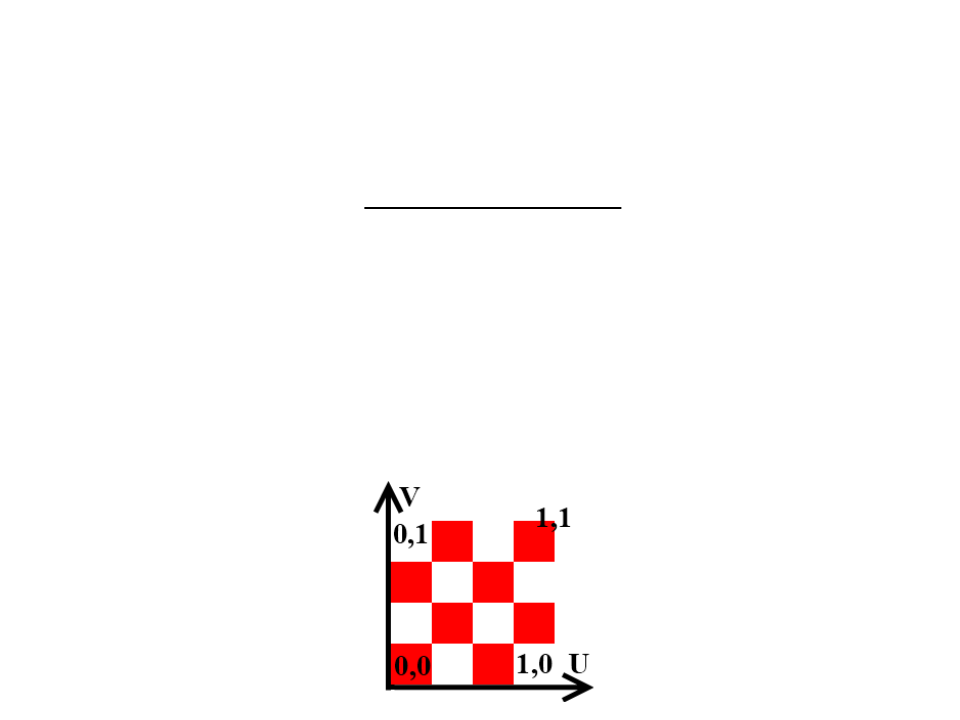
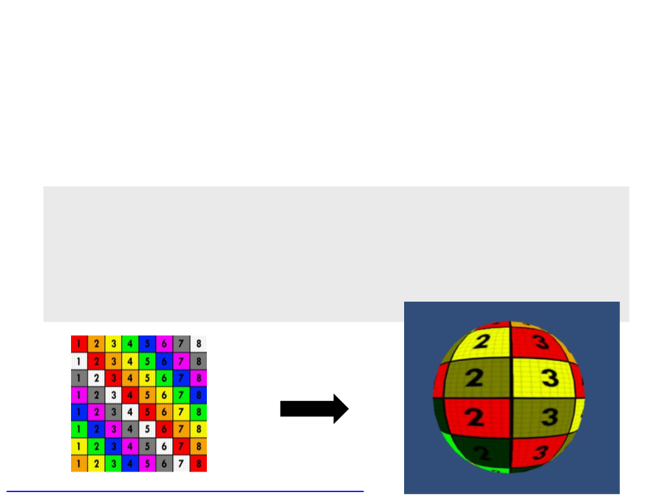
Texturing
•
•
Texturing consists of projecting an image onto the triangles of
a mesh.
Texture coordinates are used to control the projection. These
coordinates are 2D pairs that cover the entire image in a one-
unit square area.
–
The horizontal coordinate is known as U and the vertical coordinate as
V (UV coordinates).
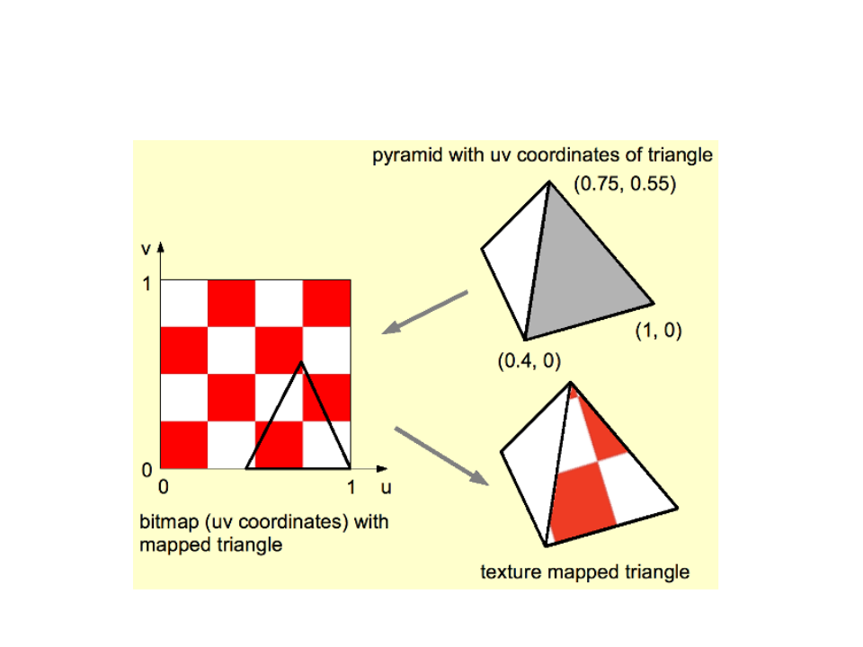
Texturing

Texturing
•
Unity's default meshes have UV coordinates and the vertex
program can access them.
struct VertexData {
float4 position : POSITION;
float2 uv : TEXCOORD0;
}
;
struct VertexToFragment {
float4 position : SV_POSITION;
float2 uv : TEXCOORD0;
}
;
VertexToFragment MyVertexProgram(VertexData vert){
VertexToFragment v2f;
v2f.position = UnityObjectToClipPos(vert.position);
v2f.uv = vert.uv;
return v2f;
}

Texturing
•
We need to add another shader property for the texture and
define another variable in the shader program to access the
texture (type sampler2D).
Properties
{
_
_
Color("Color", Color) = (1, 1, 1, 1)
MainTex("Texture", 2D) = "white" {}
}
CGPROGRAM
..
.
float4 _Color;
sampler2D _MainTex;
.
..
Texturing
•
Sampling the texture with the UV coordinates is done in the
fragment program, by using the tex2D function.
.
..
float4 MyFragmentProgram(VertexToFragment v2f) : SV_TARGET{
return tex2D(_MainTex, v2f.uv) * _Color;
}
.
..
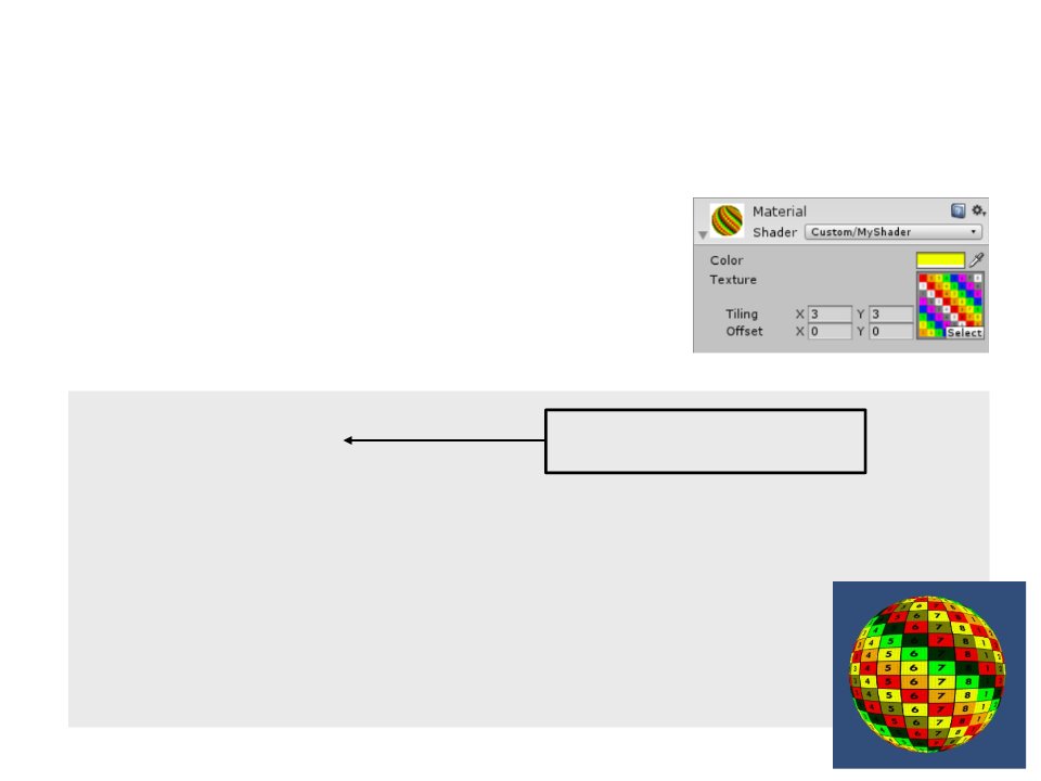
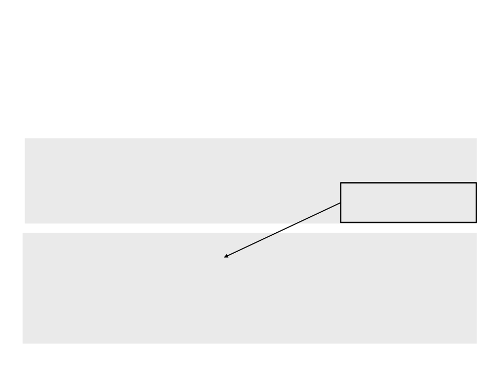
Texturing – Tiling and Offset
•
When we added a texture to our shader,
the material inspector also added tiling
and offset controls. These values can be
accessed and used by the shader.
sampler2D _MainTex;
float4 _MainTex_ST;
The same name as the
texture, plus the _ST suffix.
.
..
VertexToFragment MyVertexProgram(VertexData vert){
VertexToFragment v2f;
v2f.position = UnityObjectToClipPos(vert.position);
v2f.uv = vert.uv * _MainTex_ST.xy + _MainTex_ST.zw;
return v2f;
}
Combining Textures
•
We can also use shaders to combine textures and add more
details the surfaces of the objects.
Tiling 1x1
Texture
Tiling 10x10
Combining Texture
•
We can also use shaders to combine textures and add more
details the surfaces of the objects.
.
..
float4 MyFragmentProgram(VertexToFragment v2f) : SV_TARGET{
float4 color = tex2D(_MainTex, v2f.uv) * _Color;
color *= tex2D(_MainTex, v2f.uv * 10);
return color;
}
.
..
Combining Textures
•
When you multiply two textures together, the result will be
darker. To brighten the original texture, we can multiply the
color by 2.
.
..
float4 MyFragmentProgram(VertexToFragment v2f) : SV_TARGET{
float4 color = tex2D(_MainTex, v2f.uv) * _Color;
color *= tex2D(_MainTex, v2f.uv * 10) * 2;
return color;
}
.
..
Combining Textures
A better solution is to use a special detail texture, which is
centered around gray.
•
Tiling 1x1
Texture
Detail Texture
Tiling 10x10

Combining Textures
•
To use a second detail texture, we have to add a new texture
property to the shader.
Properties
{
_Color("Color", Color) = (1, 1, 1, 1)
_MainTex("Texture", 2D) = "white" {}
_DetailTex("Detail Texture", 2D) = "gray" {}
}
sampler2D _MainTex, _DetailTex;
float4 _MainTex_ST, _DetailTex_ST;
struct VertexToFragment {
float4 position : SV_POSITION;
float2 uv : TEXCOORD0;
float2 uvDetail : TEXCOORD1;
}
;

Combining Textures
•
To use a second detail texture, we have to add a new texture
property to the shader.
VertexToFragment MyVertexProgram(VertexData vert){
VertexToFragment v2f;
v2f.position = UnityObjectToClipPos(vert.position);
v2f.uv = vert.uv * _MainTex_ST.xy + _MainTex_ST.zw;
v2f.uvDetail = vert.uv * _DetailTex_ST.xy + _DetailTex_ST.zw;
return v2f;
}
float4 MyFragmentProgram(VertexToFragment v2f):SV_TARGET{
float4 color = tex2D(_MainTex, v2f.uv) * _Color;
color *= tex2D(_DetailTex, v2f.uvDetail) * 2;
return color;
}

Combining Textures
•
To use a second detail texture, we have to add a new texture
property to the shader.
VertexToFragment MyVertexProgram(VertexData vert){
VertexToFragment v2f;
v2f.position = UnityObjectToClipPos(vert.position);
v2f.uv = vert.uv * _MainTex_ST.xy + _MainTex_ST.zw;
v2f.uvDetail = vert.uv * _DetailTex_ST.xy + _DetailTex_ST.zw;
return v2f;
}
float4 MyFragmentProgram(VertexToFragment v2f):SV_TARGET{
float4 color = tex2D(_MainTex, v2f.uv) * _Color;
color *= tex2D(_DetailTex, v2f.uvDetail) *
unity_ColorSpaceDouble;
return color;
}
Combining Textures
Same texture multiplied
Using a separated gray detail texture
Same texture multiplied and brighter
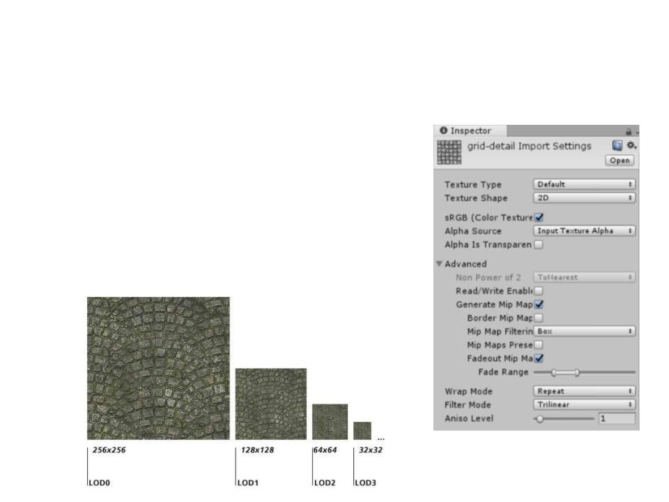
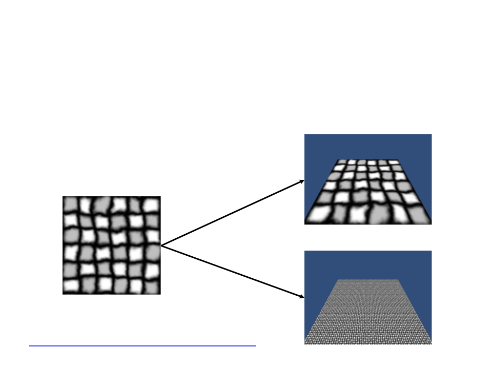
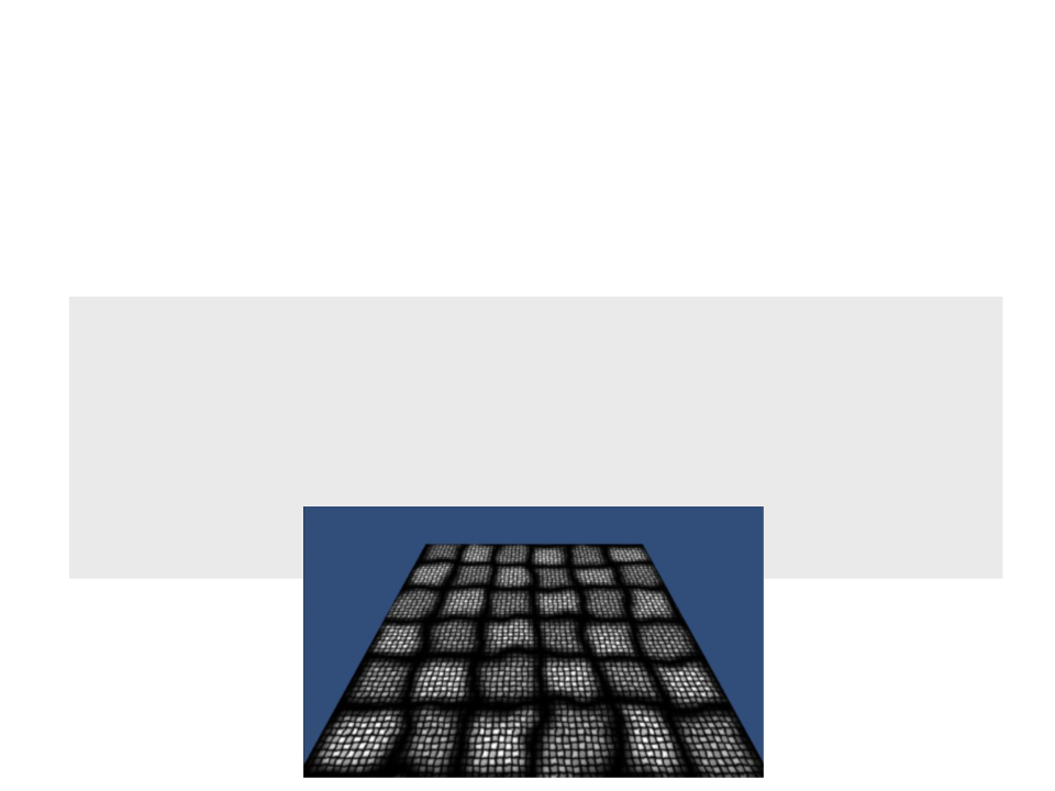
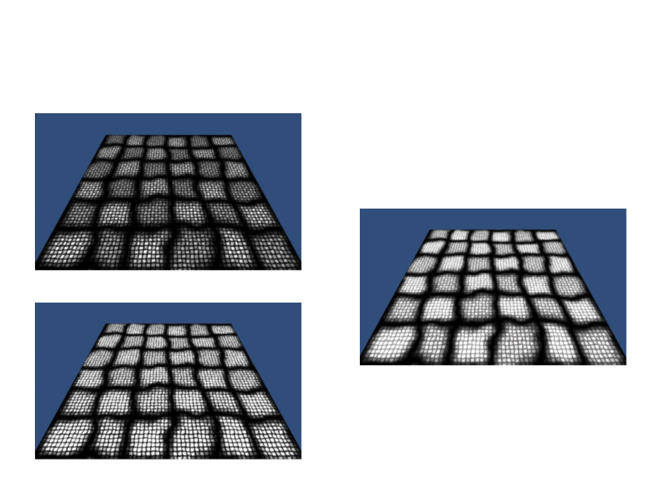
Level of Detail with Mipmaps
•
Mipmaps are pre-calculated sequences
of images with a progressively lower
resolution representation of the same
image.
–
They are intended to increase rendering
speed and reduce aliasing artifacts.
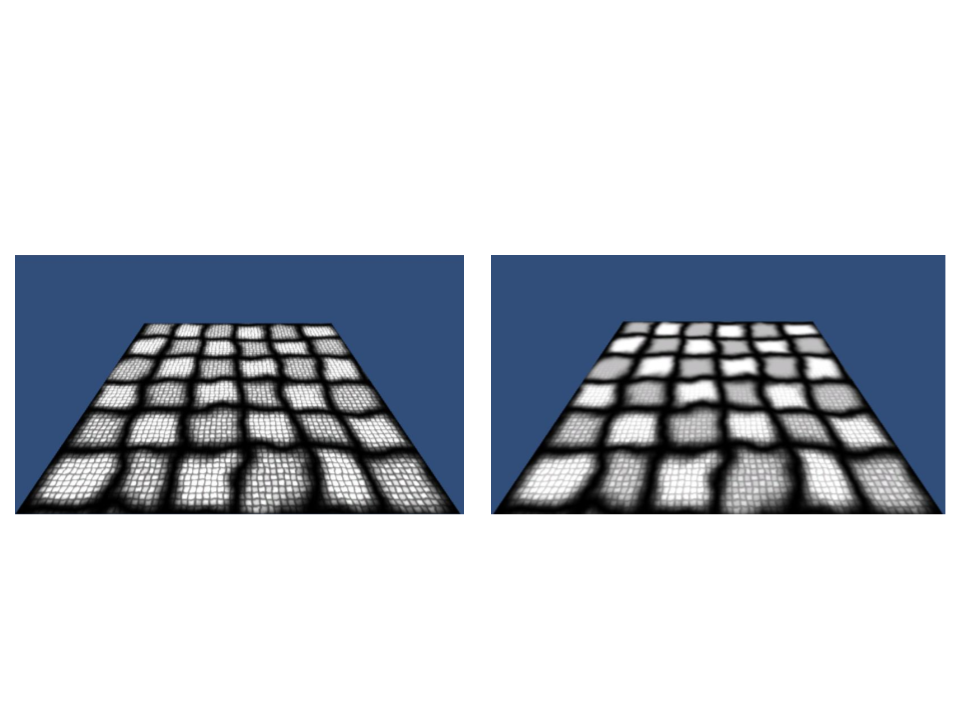
Level of Detail with Mipmaps
Without Mipmaps
With Mipmaps
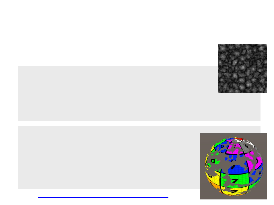
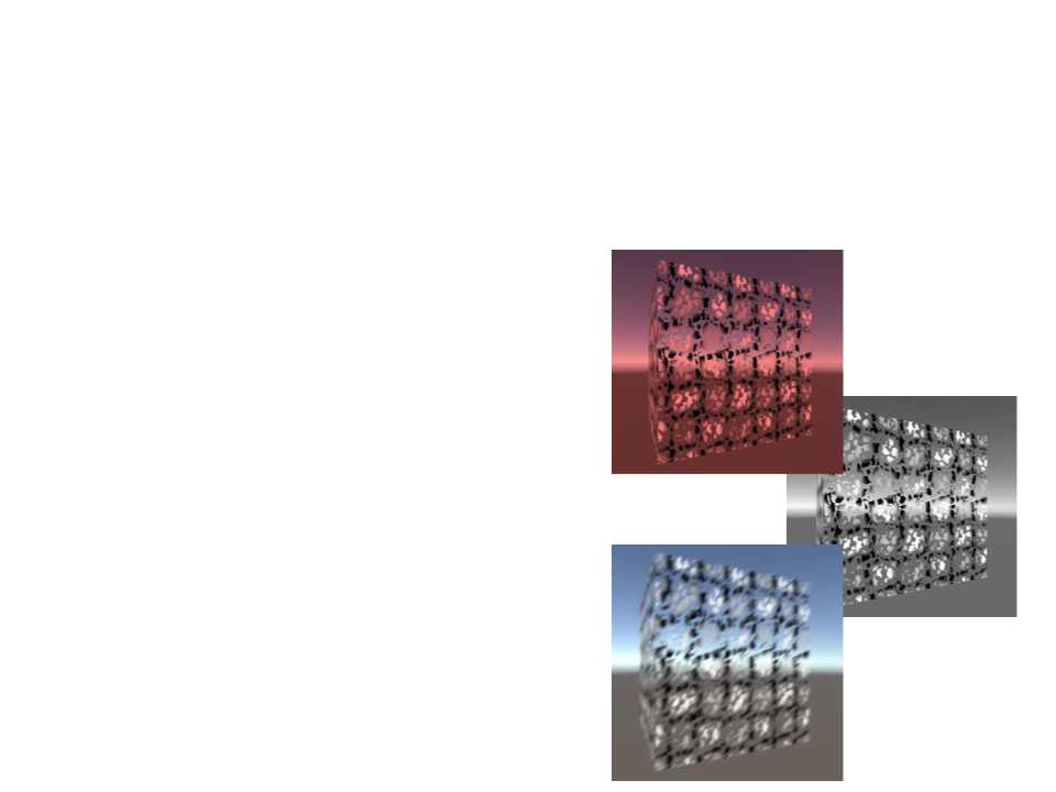
Using a Noise Texture to “Dissolve” an Object
•
We need a new texture and a float property:
Properties
{
_
_
_
_
Color("Color", Color) = (1, 1, 1, 1)
MainTex("Texture", 2D) = "white" {}
DissolveTexture ("Dissolve Texture", 2D) = "white" {}
DissolveCutoff ("Dissolve Cutoff", Range(0, 1)) = 1
}
sampler2D _MainTex, _DissolveTexture;
float4 _MainTex_ST;
float _DissolveCutoff;
struct VertexToFragment {
float4 position : SV_POSITION;
float2 uv : TEXCOORD0;
}
;

Using a Noise Texture to “Dissolve” an Object
•
The clip function checks if the given value is less than 0. If it is,
then it discards the pixel and draw nothing. If it isn’t it, keeps
the pixel and continue as normal.
VertexToFragment MyVertexProgram(VertexData vert) {
VertexToFragment v2f;
v2f.position = UnityObjectToClipPos(vert.position);
v2f.uv = vert.uv * _MainTex_ST.xy + _MainTex_ST.zw;
return v2f;
}
float4 MyFragmentProgram(VertexToFragment v2f) : SV_TARGET{
float4 textureColor = tex2D(_MainTex, v2f.uv) * _Color;
float4 dissolveColour = tex2D(_DissolveTexture, v2f.uv);
clip(dissolveColour.rgb - _DissolveCutoff);
return texturecolor;
}
Manipulating Vertices
•
•
The Vertex Shader allows us to manipulate each vertex
individually.
Simple example:
Moves all
vertices to
the right.
VertexToFragment MyVertexProgram(VertexData vert){
VertexToFragment v2f;
vert.position.x += 1;
v2f.position = UnityObjectToClipPos(vert.position);
v2f.uv = vert.uv * _MainTex_ST.xy + _MainTex_ST.zw;
return v2f;
}

Manipulating Vertices
•
Unity provides some handful of built-in variables that allow us
to access some important values in a shader. One of these
variables is the time:
_Time : float4 - running time as float4 (t/20, t, t*2, t*3)
VertexToFragment MyVertexProgram(VertexData vert){
VertexToFragment v2f;
vert.position.x += sin((_Time.y*3)+(vert.position.y*5))*0.1;
v2f.position = UnityObjectToClipPos(vert.position);
v2f.uv = vert.uv * _MainTex_ST.xy + _MainTex_ST.zw;
return v2f;
}
Exercise 1
1
) The code that implements the deformation in the object is
using some constants (3, 5, 0.1) to determine how the object
is deformed. Change the shader code to use parameterized
properties instead of constant values.
.
..
vert.position.x += sin((_Time.y * 3)+(vert.position.y * 5)) * 0.1;
..
.

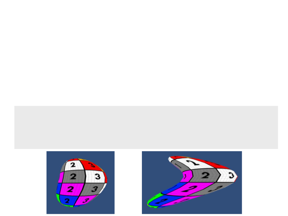
Extruding Objects
•
Extrusion push the faces of the objects in or out.
Properties{
.
..
_ExtrudeAmount("Extrude Amount", float) = 0
}
.
..
float _ExtrudeAmount;
struct VertexData {
.
..
float3 normal : NORMAL;
}
;
VertexToFragment MyVertexProgram(VertexData vert) {
VertexToFragment v2f;
vert.position.xyz += vert.normal.xyz * _ExtrudeAmount;
v2f.position = UnityObjectToClipPos(vert.position);
v2f.uv = vert.uv * _MainTex_ST.xy + _MainTex_ST.zw;
return v2f;
}

Accessing Shaders Properties by Script
public class ExtrusionAnimator : MonoBehaviour
{
private Renderer render;
void Start()
{
render = GetComponent<Renderer>();
}
void Update ()
{
render.material.SetFloat("_ExtrudeAmount", Time.time);
}
}
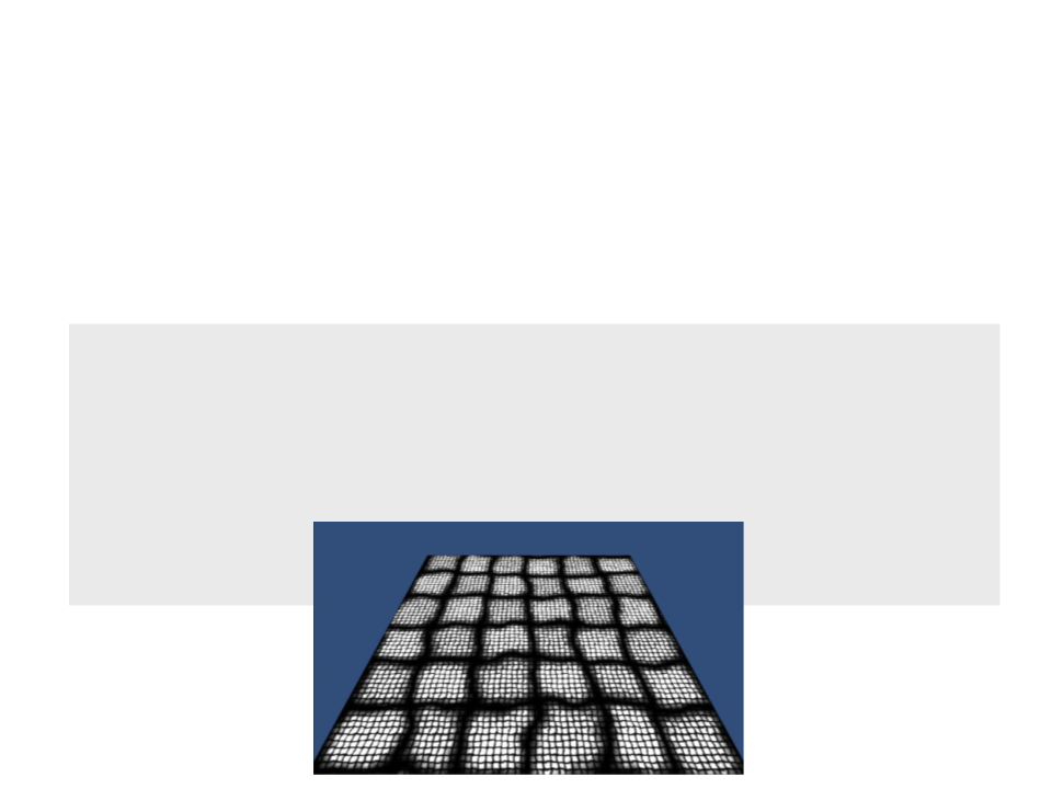
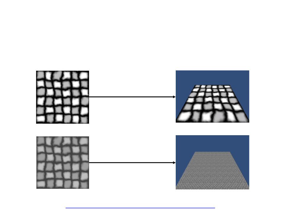
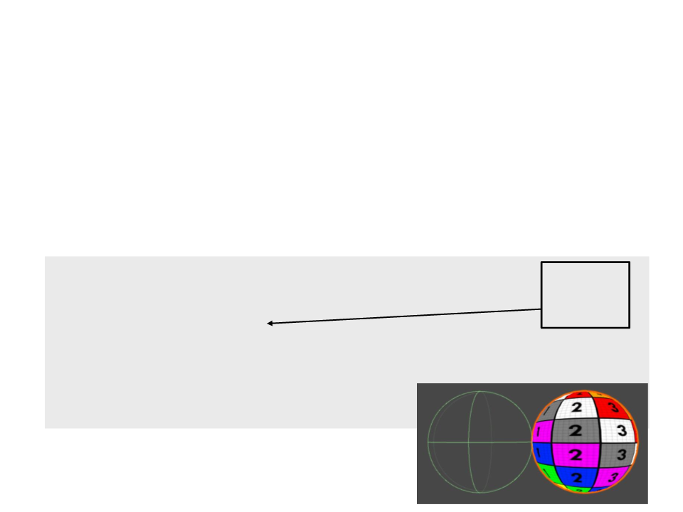
Manipulating Vertices
•
We can also use the information of an image to manipulate
the vertices an object.
Properties
{
_
_
_
Color("Color", Color) = (1, 1, 1, 1)
MainTex("Texture", 2D) = "white" {}
DeformTex("Detail Texture", 2D) = "gray" {}
Lookup the color values
of a 2D texture.
}
VertexToFragment MyVertexProgram(VertexData vert) {
VertexToFragment v2f;
float4 deformColor = tex2Dlod(_DeformTex,float4(vert.uv.xy,0,0));
vert.position.y += deformColor.r;
v2f.position = UnityObjectToClipPos(vert.position);
v2f.uv = vert.uv * _MainTex_ST.xy + _MainTex_ST.zw;
return v2f;
}
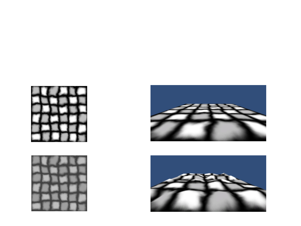
Manipulating Vertices
•
We can also use the information of an image to manipulate
the vertices an object.
Flat plane
Texture
Manipulated plane
Deformation Texture

Post-Processing Shaders – Image Effects
•
•
After a virtual camera has rendered an image, it is often
useful to apply some image post-processing to the image.
–
Artistic reasons and technical reasons.
A post-processing shader needs a shader and script file.
[
[
RequireComponent(typeof(Camera))]
ExecuteInEditMode]
public class Test : MonoBehaviour {
public Material material;
void OnRenderImage(RenderTexture source,
RenderTexture destination){
Graphics.Blit(source, destination, material);
}
}

Post-Processing Shaders – Image Effects
Shader "Image Effect/InvertColor"{
Properties{
_MainTex ("Source", 2D) = "white" {}
}
SubShader{
Cull Off
ZWrite Off
ZTest Always
Pass{
CGPROGRAM
#
#
#
pragma vertex MyVertexProgram
pragma fragment MyFragmentProgram
include "UnityCG.cginc"
sampler2D _MainTex;
float4 _MainTex_ST;

struct VertexData{
float4 position : POSITION;
float2 uv : TEXCOORD0;
}
;
struct VertexToFragment{
float4 position : POSITION;
float2 uv : TEXCOORD0;
}
;
VertexToFragment MyVertexProgram(VertexData vert){
VertexToFragment v2f;
v2f.position = UnityObjectToClipPos(vert.position);
v2f.uv = vert.uv;
return v2f;
}
float4 MyFragmentProgram(VertexToFragment v2f) : SV_TARGET{
float4 color = tex2D(_MainTex, v2f.uv);
return 1 - color;
}
ENDCG
}
}
}
Exercise 2
2) Implement image effect shaders for the following effects:
a) Add a red tone to the rendered
image;
b) Transform the rendered image
into a gray scale image;
c) Add a blur effect to the rendered
image;
Forward Rendering
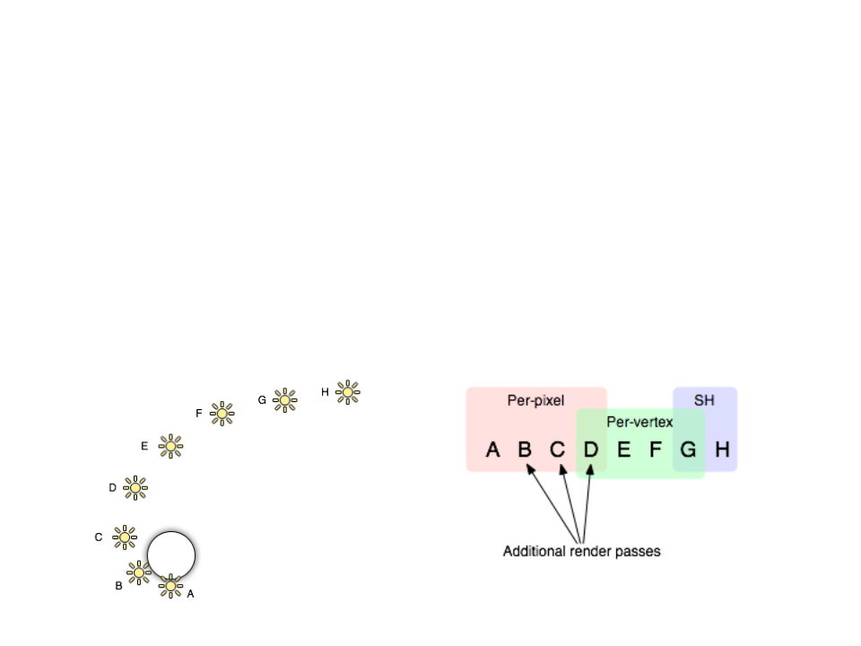
Forward Rendering
•
In Forward Rendering, lights can be rendered in 3 different ways:
–
Some lights that affect each object are rendered in fully per-pixel mode
(number defined by the Pixel Light Count – Quality Setting).
–
–
Up to 4 point lights are calculated per-vertex.
The other lights are computed as spherical harmonics (SH – faster
method, but is only an approximation).
Note: groups overlap reduces the "light popping" effect.
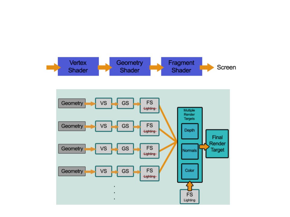
Deferred Rendering
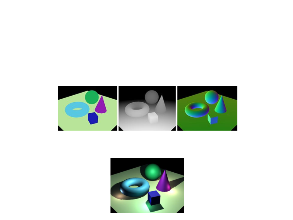
Deferred Rendering
•
In Deferred Rendering, each object is rendered once on the first pass and
shading information is stored into G-buffer textures using multiple render
targets (MRT).
Color
Depth
Normal
•
Additional passes compute lighting based on G-buffer information in
screen space:
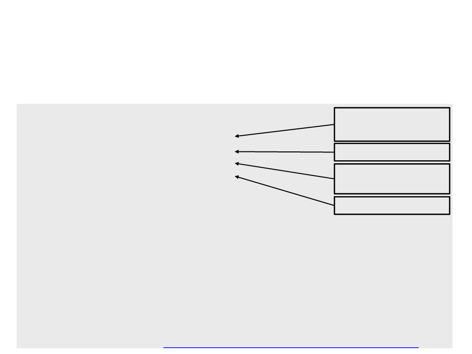
Deferred Shaders
The main difference between a forward shader and deferred
shader is the output of the fragment program:
•
struct FragmentOutput{
Diffuse albedo and
the surface occlusion.
#
if defined(DEFERRED_PASS)
float4 gBuffer0 : SV_Target0;
float4 gBuffer1 : SV_Target1;
float4 gBuffer2 : SV_Target2;
float4 gBuffer3 : SV_Target3;
else
Specular color.
World-space normal
vectors.
#
float4 color : SV_Target;
#endif
Emission lighting.
}
;
FragmentOutput MyFragmentProgram (Interpolators i) {
FragmentOutput output;
#
#
#
if defined(DEFERRED_PASS)
/fill the buffers
else
output.color = color;
endif
/
return output;
}
Implementation Tutorial: http://catlikecoding.com/unity/tutorials/rendering/part-13/
Further Reading
•
Hughes, J. F., et al. (2013). Computer Graphics: Principles and Practice
(
0
3rd ed.). Upper Saddle River, NJ: Addison-Wesley Professional. ISBN: 978-
-321-39952-6.
–
Chapter 33: Shaders
•
Web:
–
http://catlikecoding.com/unity/tutorials/rendering/part-2/
–
http://catlikecoding.com/unity/tutorials/rendering/part-3/