
Computer Graphics
Lecture 04 – 3D Projection and Visualization
Edirlei Soares de Lima
<edirlei.lima@universidadeeuropeia.pt>
Projection and Visualization
•
•
An important use of geometric transformations in computer
graphics is in moving objects between their 3D locations and
their positions in a 2D view of the 3D world.
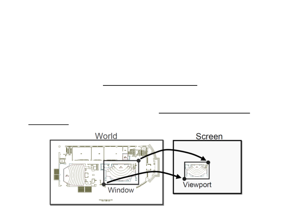
This 3D to 2D mapping is called a viewing transformation or
projection.

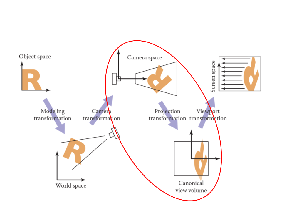
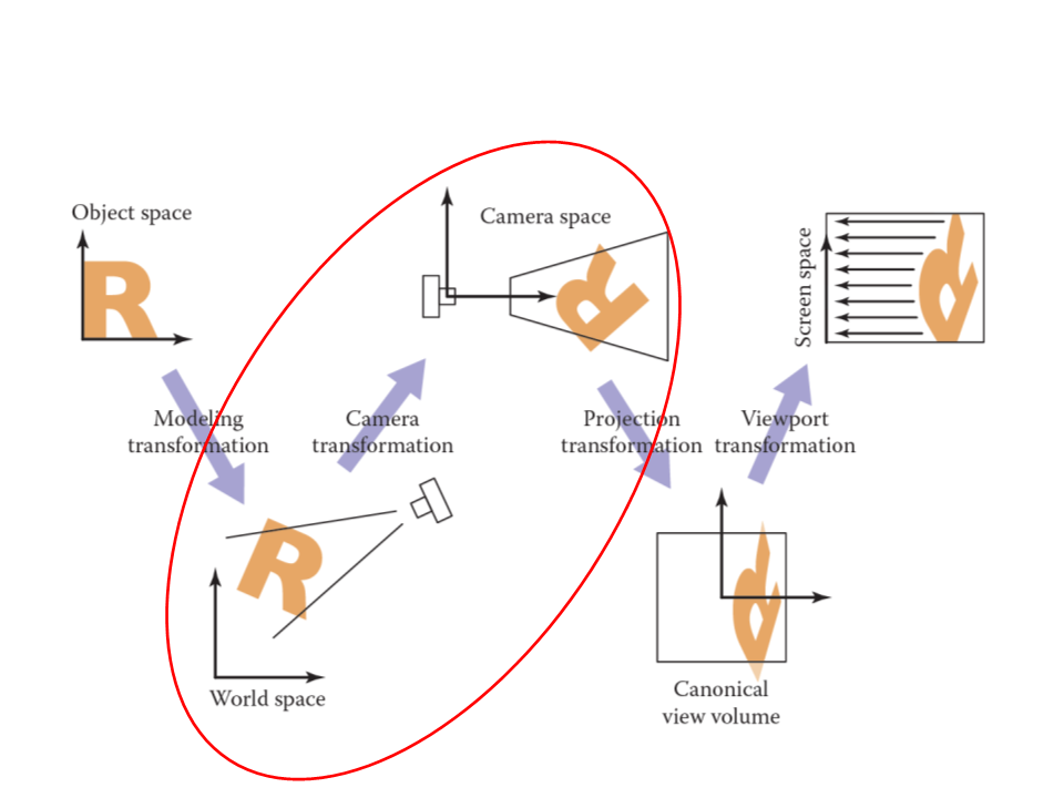
Viewing Transformations
•
•
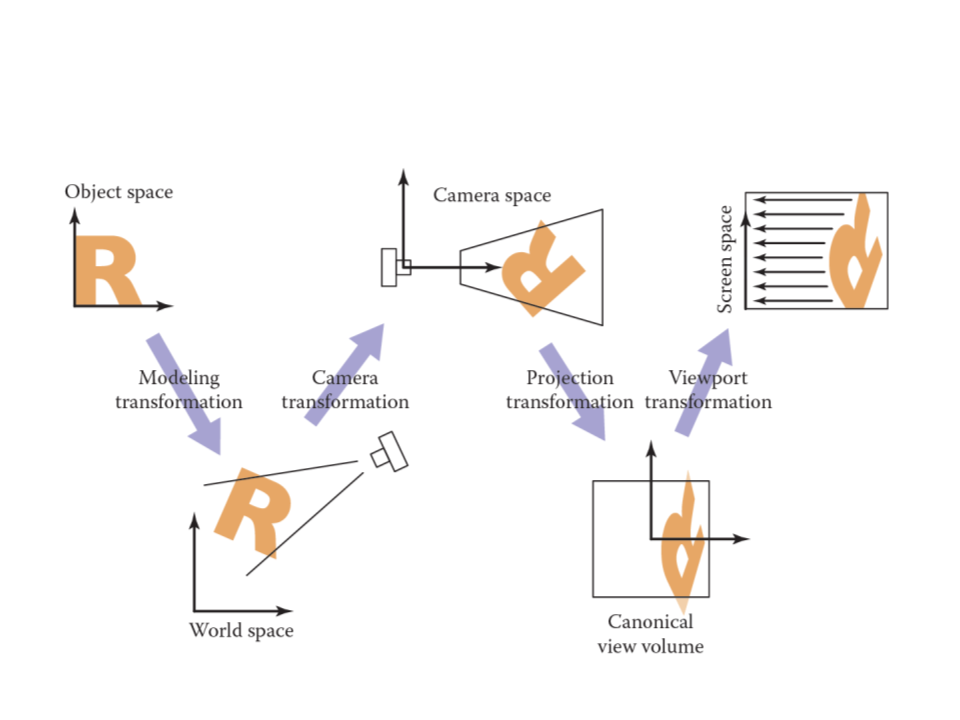
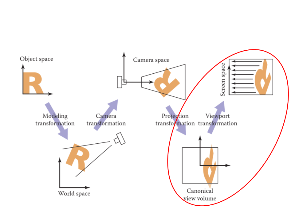
The viewing transformation has the objective of mapping 3D
coordinates (represented as [x, y, z] in the canonical
coordinate system) to coordinates in the screen (expressed in
units of pixels).
–
Important factors: camera position and orientation, type of
projection, screen resolution, field of view.
Transformations:
–
–
–
Camera Transformation: converts points in canonical coordinates (or
world space) to camera coordinates;
Projection Transformation: moves points from camera space to the
canonical view volume;
Viewport Transformation: maps the canonical view volume to screen
space.
Viewing Transformations
Viewing Transformations
•
•
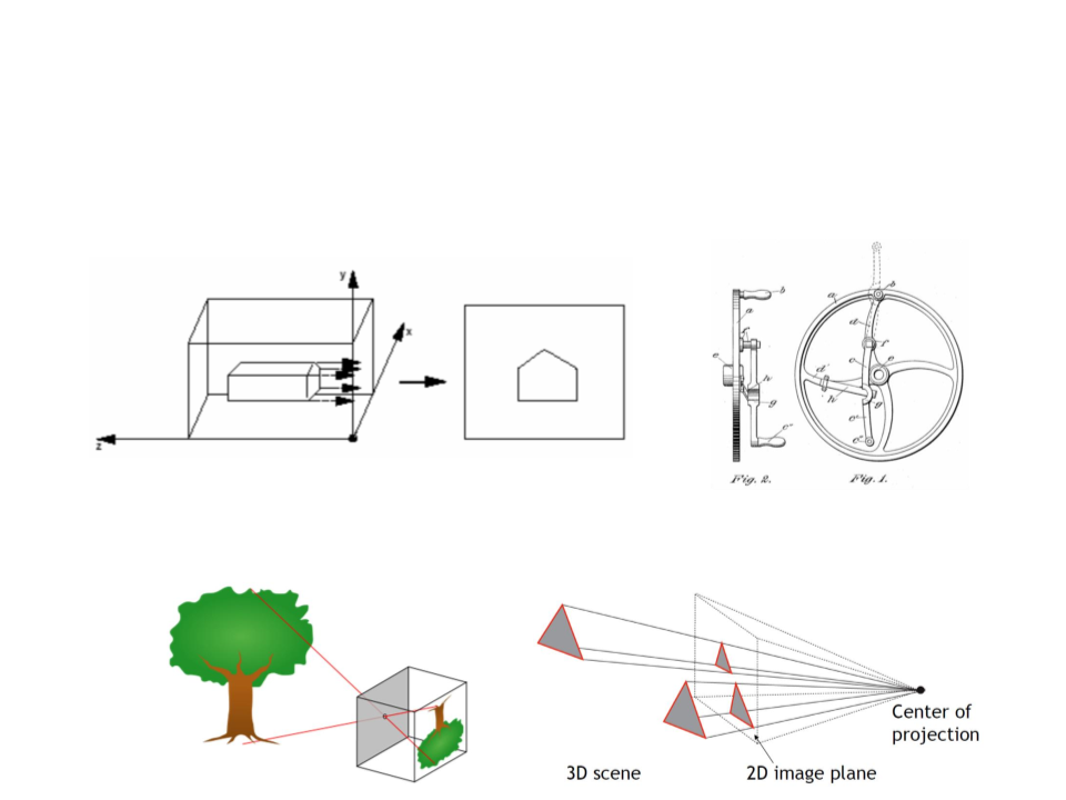
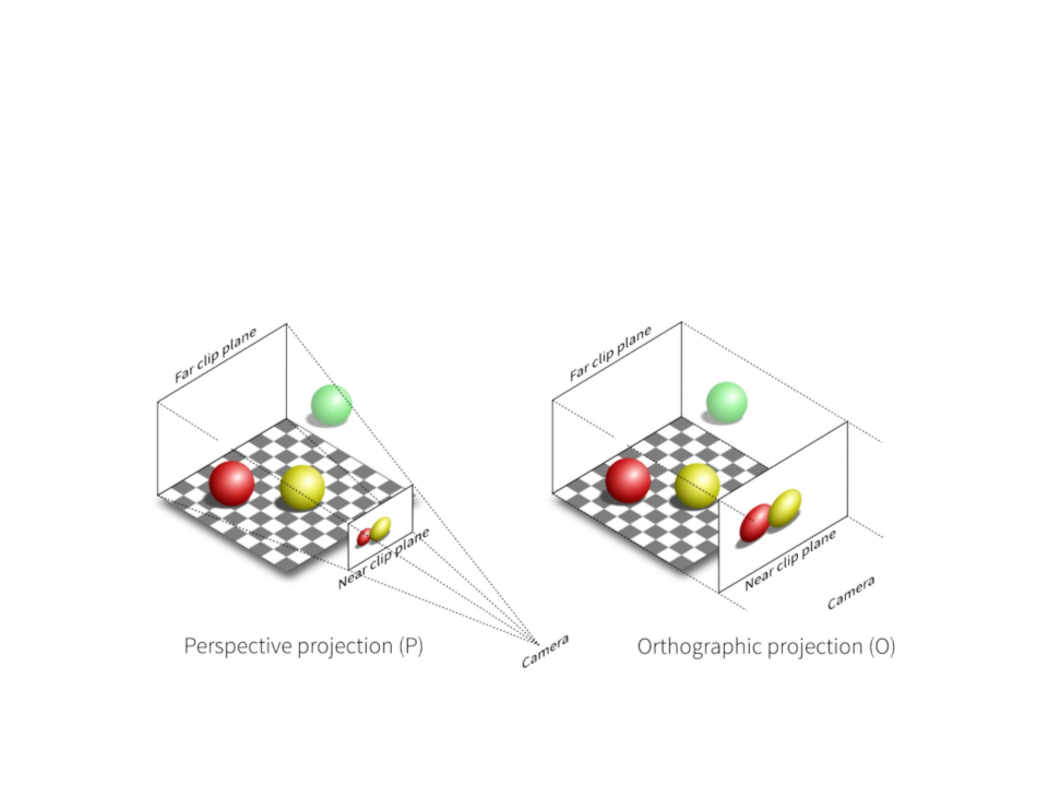
Orthographic Projection: can be done by ignoring z-coordinate.
Perspective Projection: simplified model of human eye, or
camera lens (pinhole camera).
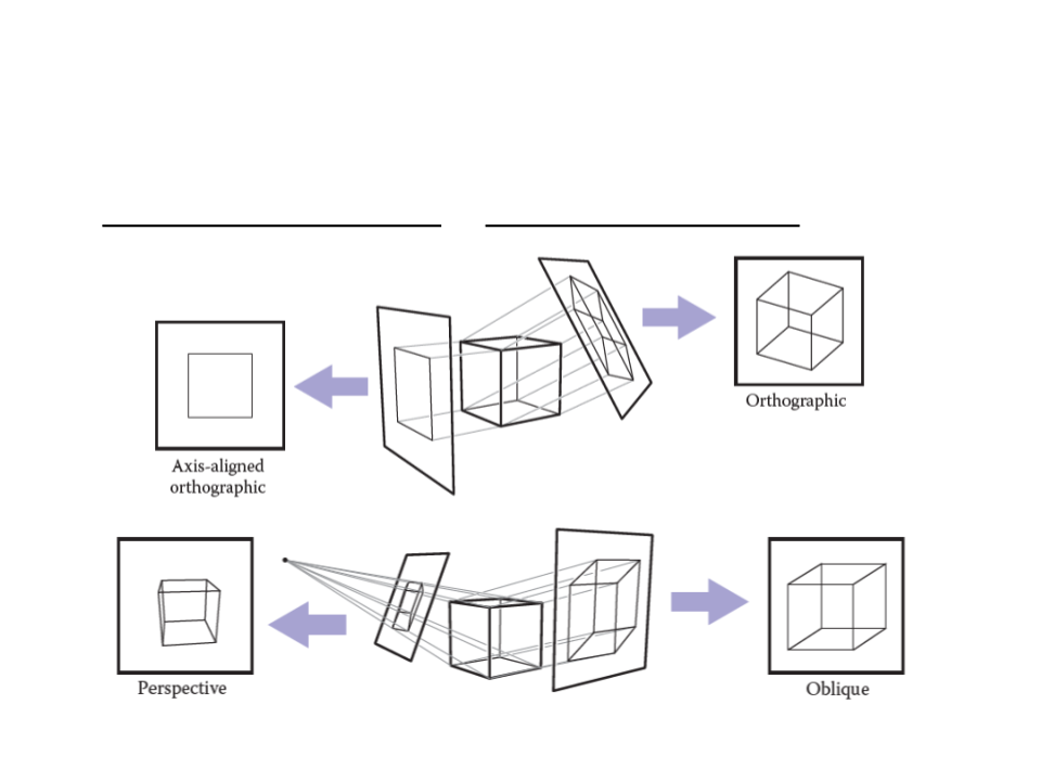
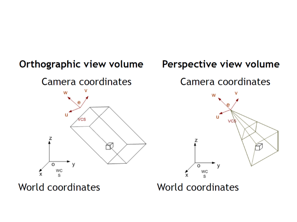
Viewing Transformations
•
Orthographic Projection vs Perspective Projection
Viewing Transformations
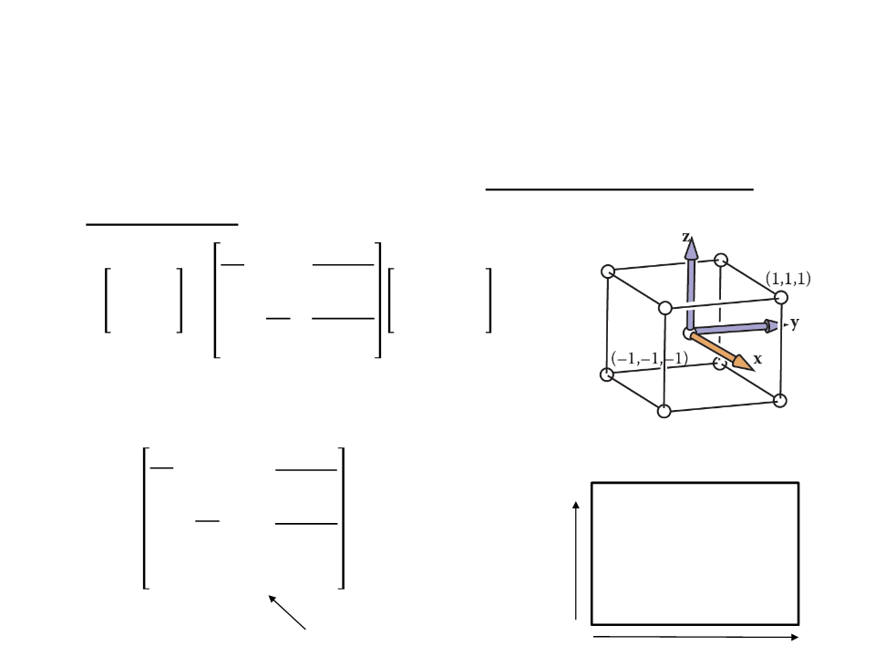
Viewport Transformation
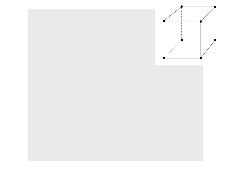
•
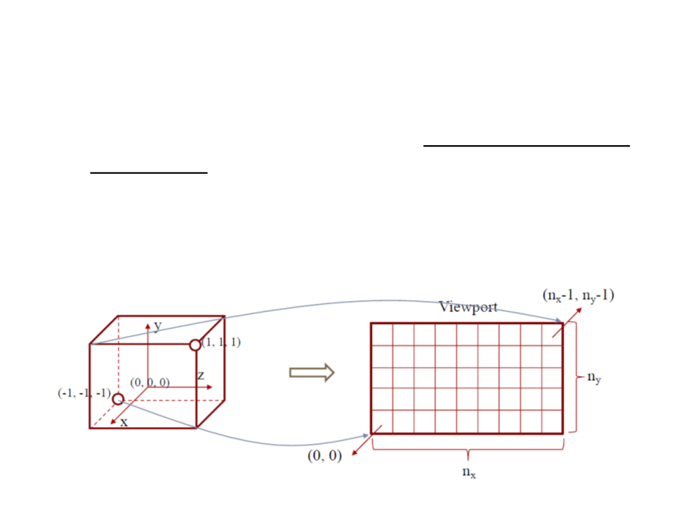
The viewport transformation maps the canonical view volume
to screen space.
–
The canonical view volume is a cube containing all 3D points whose
coordinates are between −1 and +1 (i.e. (x, y, z) ∈ [−1, 1]).
–
Considering a screen of nx by ny pixels, we need to map the square [−1,
1
] to the rectangle [0, nx] × [0, ny].
Viewport Transformation
•
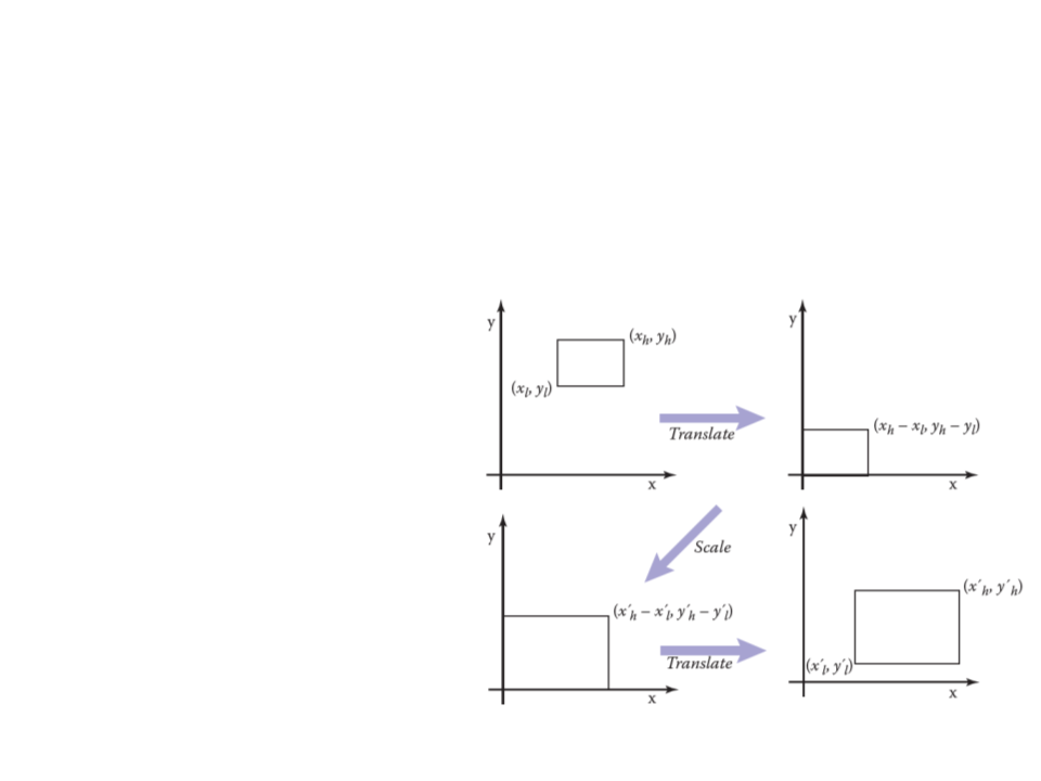
Viewport transformation is windowing transformation that
can be accomplished with three operations (2D example):
1
. Move the points (xl, yl) to
the origin.
2
. Scale the rectangle to be
the same size as the
target rectangle.
3
. Move the origin to point
(x’l, y’l).
Viewport Transformation
•
These operations can be represented as multiplications of
matrices (2D example):
ꢁ
ꢂℎ − ꢁꢂꢃ
0
0
1
0
0
0 ꢁꢂꢃ ꢁℎ − ꢁꢃ
1 ꢄꢂꢃ
1 0 −ꢁꢃ
0 1 −ꢄꢃ
ꢀ
=
ꢄꢂℎ − ꢄꢂꢃ
0
0
1
0
0 1
0 1
ꢄℎ − ꢄꢃ
0
0
ꢁ
ꢂℎ − ꢁꢂꢃ
ꢁꢂꢃꢁℎ − ꢁꢂℎꢁꢃ
ꢁℎ − ꢁꢃ
0
ꢁℎ − ꢁꢃ
ꢀ
=
ꢄꢂℎ − ꢄꢂꢃ ꢄꢂꢃꢄℎ − ꢄꢂℎꢄꢃ
0
0
ꢄℎ − ꢄꢃ
0
ꢄℎ − ꢄꢃ
1
Viewport Transformation
•
•
Back to our 3D problem: map the canonical view volume to
screen space.
ꢊꢋ
ꢊꢋ − 1
0
ꢁꢅꢆꢇꢈꢈꢉ
ꢁꢆꢍꢉꢎꢉꢏꢆꢍꢃ
ꢄꢆꢍꢉꢎꢉꢏꢆꢍꢃ
1
2
2
ꢄꢅꢆꢇꢈꢈꢉ
=
ꢊꢌ ꢊꢌ − 1
0
0
1
2
0
2
1
In homogeneous coordinates:
ꢊꢋ
2
ꢊꢋ − 1
0
0
(ꢊꢋ, ꢊꢌ)
(0, ꢊꢌ)
2
ꢊꢌ − 1
ꢊꢌ
ꢐꢑꢒ =
0
0
2
0 1
0 0
2
0
1
0
0
keeps the z-coordinate
(ꢊꢋ, 0)
(0,0)
Viewing Transformations

Projection Transformation
•
•
The projection transformation moves points from camera
space to the canonical view volume.
This is a very important step, because we usually want to
render geometry in some region of space other than the
canonical view volume.
•
The simplest type of projection is parallel projection, in which
3
projection direction until they hit the image plane.
D points are mapped to 2D by moving them along a
–
In the orthographic projection, the image plane is perpendicular to the
view direction.
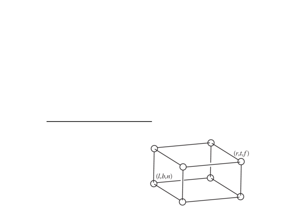
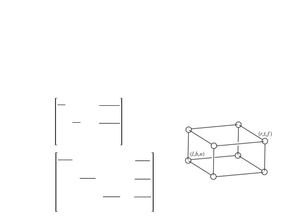
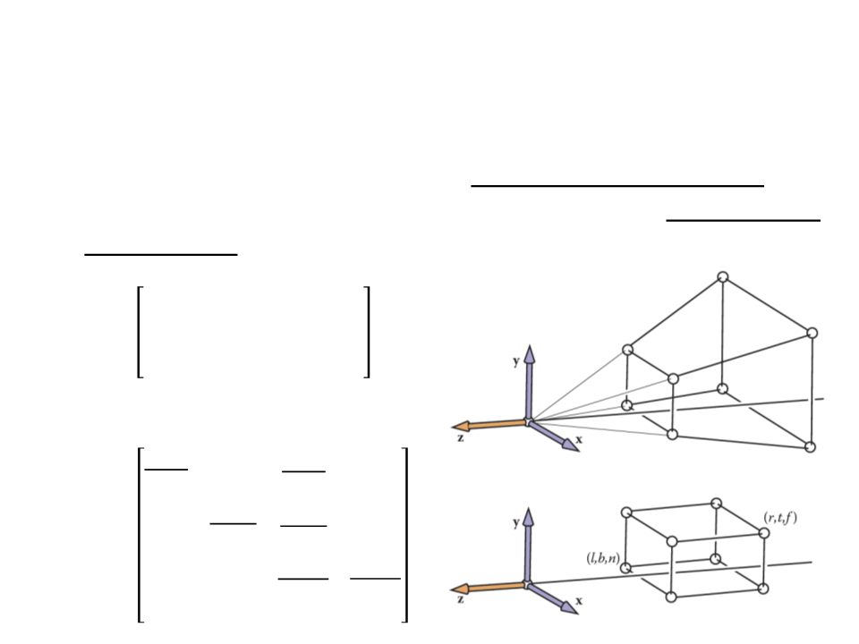
Orthographic Projection
•
•
Our first step in generalizing the view will keep the view
direction and orientation fixed looking along −z with +y up,
but will allow arbitrary rectangles to be viewed.
The orthographic view volume is an axis-aligned box [l, r] × [b,
t] × [f, n].
x = l ≡ left plane
x = r ≡ right plane
y = b ≡ bottom plane
y = t ≡ top plane
z = n ≡ near plane
z = f ≡ far plane
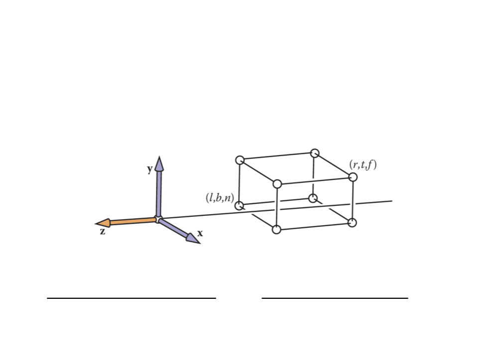
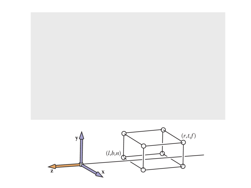
Orthographic Projection
•
We assume a viewer who is looking along the minus z-axis with
his head pointing in the y-direction. This implies that n > f.
•
How can we transform points that are inside of the
orthographic view volume to the canonical view volume?
–
This transform is another windowing transformation!
Orthographic Projection
•
•
Orthographic projection matrix:
2
ꢔ + ꢕ
0
0
− ꢔ − ꢕ
ꢔ − ꢕ
2
ꢖ − ꢗ
0
ꢖ + ꢗ
0
0
0
2
−
ꢐꢎꢇꢓℎ
=
ꢖ − ꢗ
ꢊ + ꢘ
ꢊ − ꢘ − ꢊ − ꢘ
0
0
0
1
The ꢐꢎꢇꢓℎ matrix can be combined with ꢐꢑꢒ matrix to
transform points to screen coordinates:
ꢁꢅꢆꢇꢈꢈꢉ
ꢄꢅꢆꢇꢈꢈꢉ
ꢙꢆꢍꢉꢉꢎꢉꢏꢆꢍꢃ
ꢁ
ꢄ
ꢙ
=
ꢐꢑꢒꢐꢎꢇꢓℎ
1
1

Orthographic Projection
•
Now we can start the implementation of the code to draw
objects on screen (only lines):
construct Mvp
construct Morth
M = MvpMorth
for each line segment (ai, bi) do
p = Mai
q = Mbi
drawline(xp, yp, xq, yq)
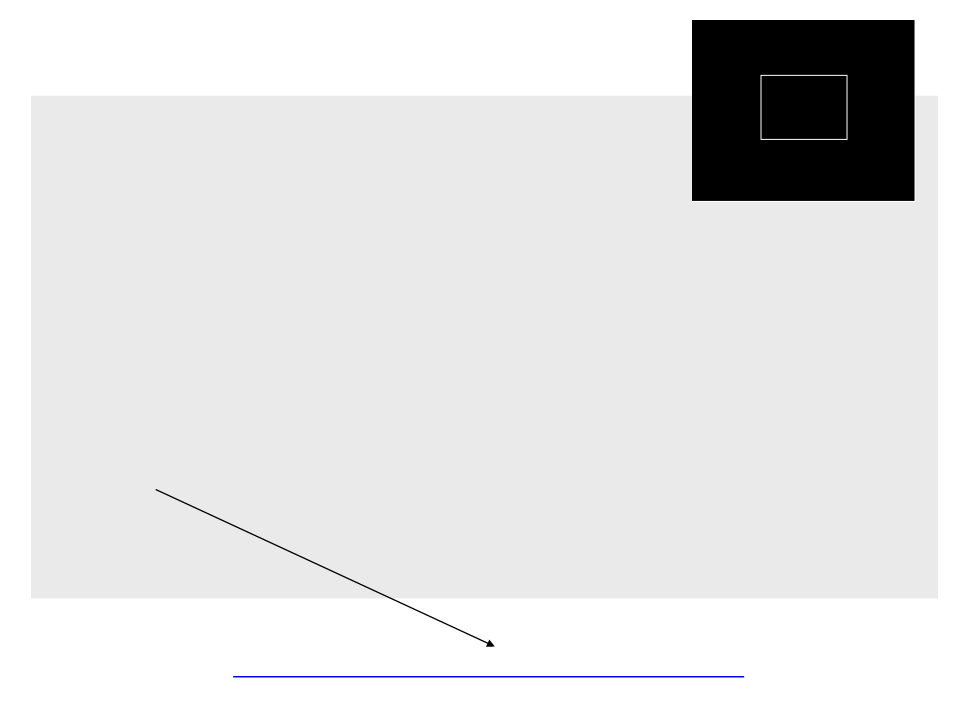
•
In order to test the orthographic projection in Unity, first we
need to simulate the world space and create the mesh of a 3D
object.

p7
p3
p6
p2
.
..
p4
p0
p5
public class World : MonoBehaviour{
private Mesh mesh;
public Vector3[] vertices;
public int[] lines;
void Start()
{
p1
mesh = new Mesh();
GetComponent<MeshFilter>().mesh = mesh;
mesh.name = "MyMesh";
Vector3 p0 = new Vector3(-1f, -1f, -1f);
Vector3 p1 = new Vector3(1f, -1f, -1f);
Vector3 p2 = new Vector3(1f, -1f, -3f);
Vector3 p3 = new Vector3(-1f, -1f, -3f);
Vector3 p4 = new Vector3(-1f, 1f, -1f);
Vector3 p5 = new Vector3(1f, 1f, -1f);
Vector3 p6 = new Vector3(1f, 1f, -3f);
Vector3 p7 = new Vector3(-1f, 1f, -3f);
...

p7
p3
p6
p2
.
..
p4
p0
p5
vertices = new Vector3[]
{
/
/ Bottom
p0, p1, p2, p3,
/ Left
p7, p4, p0, p3,
/ Front
p4, p5, p1, p0,
/ Back
p6, p7, p3, p2,
/ Right
p5, p6, p2, p1,
/ Top
p7, p6, p5, p4
/
p1
/
/
/
/
};
...
p7
p3
p6
p2
p4
p0
p5
.
..
int[] triangles = new int[]
{
3
3
7
7
1
1
1
1
1
1
2
2
, 1, 0, // Bottom
, 2, 1,
, 5, 4, // Left
, 6, 5,
1, 9, 8, // Front
1, 10, 9,
5, 13, 12, // Back
5, 14, 13,
9, 17, 16, // Right
9, 18, 17,
3, 21, 20, // Top
3, 22, 21,
p1
};
...

p7
p3
p6
p2
.
lines = new int[]
{
..
p4
p0
p5
0, 1,
0, 3,
0, 5,
1, 2,
1, 9,
2, 3,
2, 12,
3, 4,
5, 9,
5, 4,
9, 12,
12, 4
p1
};
mesh.vertices = vertices;
mesh.triangles = triangles;
mesh.RecalculateNormals();
}
}
Orthographic Projection
•
After simulating the world space, we need to:
–
–
–
Define the orthographic view volume;
Construct the ꢐꢑꢒ and ꢐꢎꢇꢓℎ matrices;
Draw the objects in screen space.
ꢊꢋ
ꢊꢋ − 1
0
0
2
2
ꢊꢌ − 1
orthographic view volume
ꢊꢌ
ꢐꢑꢒ =
0
0
2
0 1
0 0
2
0
1
0
0
2
ꢔ + ꢕ
0
0
− ꢔ − ꢕ
ꢖ + ꢗ
ꢔ − ꢕ
2
ꢖ − ꢗ
0
0
0
0
2
− ꢖ − ꢗ
ꢊ + ꢘ
ꢊ − ꢘ − ꢊ − ꢘ
ꢐꢎꢇꢓℎ
=
0
0
0
1
...
public class ViewTrasform : MonoBehaviour {
public World world;
private float left_plane = 5f;
private float right_plane = -5f;
private float botton_plane = -5f;
private float top_plane = 5f;
private float near_plane = -1f;
private float far_plane = -11f;
private Texture2D frameBuffer;
...

...
void OnGUI()
{
Matrix4x4 mvp = new Matrix4x4();
mvp.SetRow(0,new Vector4(Screen.width/2f,0f,0f,(Screen.width-1)/2f));
mvp.SetRow(1,new Vector4(0f,Screen.height/2f,0f,(Screen.height-1)/2f));
mvp.SetRow(2,new Vector4(0f, 0f, 1f, 0f));
mvp.SetRow(3,new Vector4(0f, 0f, 0f, 1f));
Matrix4x4 morth = new Matrix4x4();
morth.SetRow(0, new Vector4(2f / (right_plane - left_plane), 0f, 0f,
-
((right_plane+left_plane)/(right_plane-left_plane))));
morth.SetRow(1, new Vector4(0f, 2f / (top_plane - botton_plane), 0f,
((top_plane + botton_plane) / (top_plane - botton_plane))));
morth.SetRow(2, new Vector4(0f, 0f, 2f / (near_plane - far_plane),
((near_plane + far_plane) / (near_plane - far_plane))));
-
-
morth.SetRow(3, new Vector4(0f, 0f, 0f, 1f));
Matrix4x4 m = mvp * morth;
ClearBuffer(frameBuffer, Color.black);
...
...
for (int i = 0; i < world.lines.Length; i+=2)
{
Vector4 p = multiplyPoint(m,
new Vector4(world.vertices[world.lines[i]].x,
world.vertices[world.lines[i]].y,
world.vertices[world.lines[i]].z, 1));
Vector4 q = multiplyPoint(m,
new Vector4(world.vertices[world.lines[i + 1]].x,
world.vertices[world.lines[i + 1]].y,
world.vertices[world.lines[i + 1]].z, 1));
DrawLine(frameBuffer, (int)p.x, (int)p.y, (int)q.x, (int)q.y,
Color.white);
}
}

Matrix by Point Multiplication
Vector4 multiplyPoint(Matrix4x4 matrix, Vector4 point)
{
Vector4 result = new Vector4();
for (int r = 0; r < 4; r++)
{
float s = 0;
for (int z = 0; z < 4; z++)
s += matrix[r, z] * point[z];
result[r] = s;
}
return result;
}
Note: we could also use the function Matrix4x4.MultiplyPoint(Vector3 point), but
it multiplies the matrix by a Vector3 and returns another Vector3. For now this is
not a problem, but it will be a problem when we need the w coordinate to do
perspective projection.
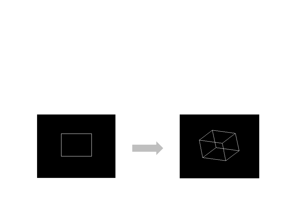
Exercise 1
1
) How do you know that the resulting rectangle on screen is
correct? Use the rotation transformations to rotate the
object and see if it looks 3D.
Viewing Transformations
Camera Transformation
•
•
The camera transformation converts points in world space to
camera coordinates.
–
This transformation allow us to change the viewpoint in 3D and look in
any direction.
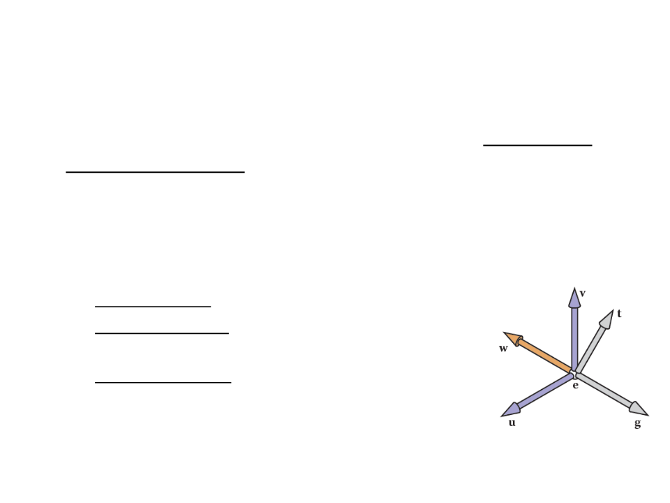
Camera specification:
–
Eye position (e): location that the eye “sees from”;
–
Gaze direction (g): vector in the direction that the
viewer is looking;
–
View-up vector (t): vector in the plane that both
bisects the viewer’s head into right and left halves
(for a person standing on the ground, it points “to
the sky”).
Camera Transformation
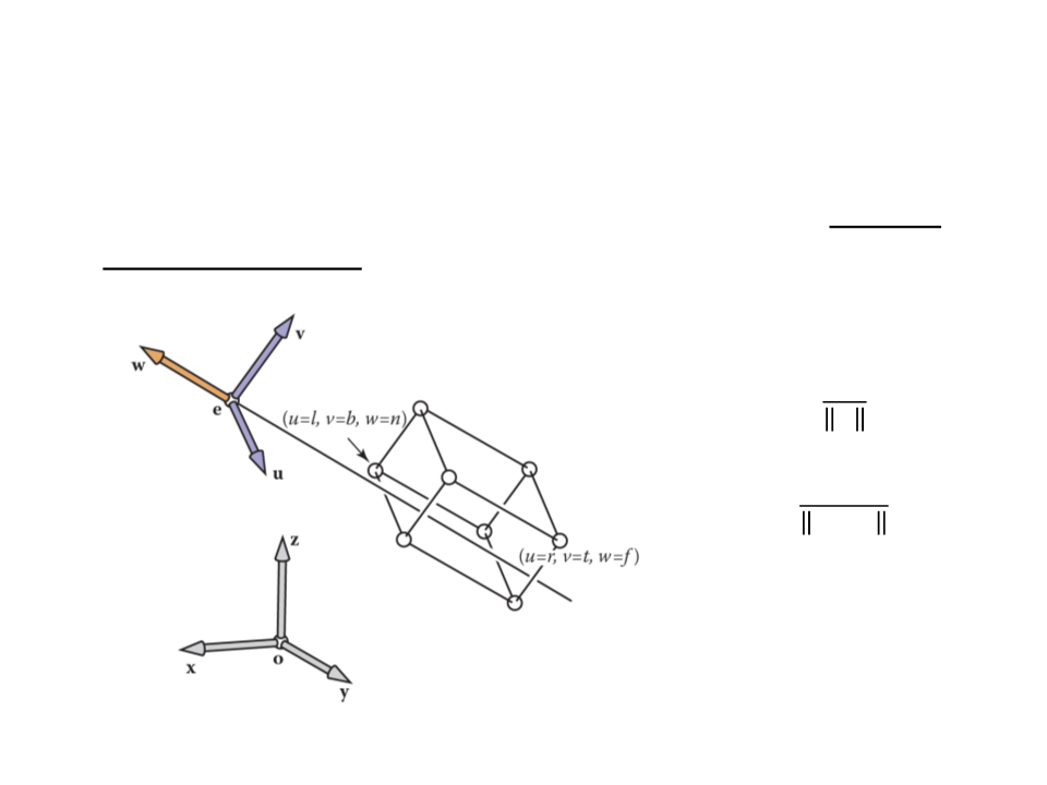
•
The camera vectors provide enough information to set up a
coordinate system with origin e and a uvw basis.
ꢛ
ꢚ = −
ꢛ
ꢖ × ꢚ
ꢜ =
ꢖ × ꢚ
ꢝ = ꢜ × ꢚ
Camera Transformation
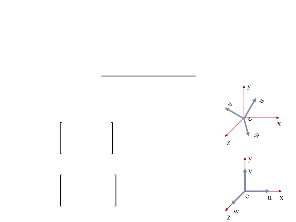
•
After set up the coordinate system with origin e and a uvw
basis, we need to convert the coordinates of the objects from
xyz-coordinates into uvw-coordinates.
–
Step 1: Translate e to the world origin (0, 0, 0);
1
0
0
0
0 0 −ꢁꢈ
1 0 −ꢄꢈ
ꢀ
=
−
ꢚꢈ
0 1
0 0 1
–
Step 2: Rotate uvw to align it with xyz;
ꢁꢟ ꢄꢟ ꢙꢟ 0
ꢁꢑ ꢄꢑ ꢙꢑ 0
ꢁꢠ ꢄꢠ ꢙꢠ 0
ꢞ =
0
0 0 1
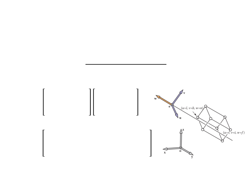
Camera Transformation
•
After set up the coordinate system with origin e and a uvw
basis, we need to convert the coordinates of the objects from
xyz-coordinates into uvw-coordinates.
ꢁꢟ ꢄꢟ ꢙꢟ 0 1 0 0 −ꢁꢈ
ꢁꢑ ꢄꢑ ꢙꢑ 0 0 1 0 −ꢄꢈ
ꢁꢠ ꢄꢠ ꢙꢠ 0 0 0 1 −ꢚꢈ
0
0 0 1 0 0 0 1
ꢐꢆꢍꢡ
=
=
ꢁꢟ ꢄꢟ ꢙꢟ −(ꢁꢟꢁꢈ + ꢄꢟꢄꢈ + ꢙꢟꢙꢈ)
ꢁꢑ ꢄꢑ
ꢙꢑ −(ꢁꢑꢁꢈ + ꢄꢑꢄꢈ + ꢙꢑꢙꢈ)
ꢐꢆꢍꢡ
ꢁꢠ
ꢄꢠ ꢙꢠ −(ꢁꢠꢁꢈ + ꢄꢠꢄꢈ + ꢙꢠꢙꢈ)
0
0 0
1

Camera Transformation
•
Now we can make the viewing algorithm work for cameras
with any location and orientation.
–
The camera transformation is added to the product of the viewport
and projection transformations, so that it converts the incoming points
from world to camera coordinates before they are projected.
construct Mvp
construct Morth
construct Mcam
M = MvpMorthMcam
for each line segment (ai, bi) do
p = Mai
q = Mbi
drawline(xp, yp, xq, yq)
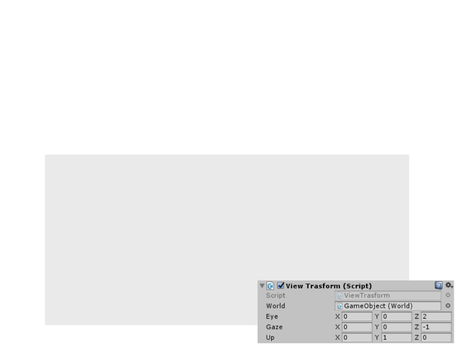
Camera Transformation
•
In order to add the camera transformation to our
implementation in Unity, first we define the camera
properties:
.
..
public class ViewTrasform : MonoBehaviour {
..
.
public Vector3 eye;
public Vector3 gaze;
public Vector3 up;
...
...
Vector3 w = -gaze.normalized;
Vector3 u = Vector3.Cross(up, w).normalized;
Vector3 v = Vector3.Cross(w, u);
Matrix4x4 mcam = new Matrix4x4();
mcam.SetRow(0, new Vector4(u.x, u.y, u.z,
-((u.x * eye.x) + (u.y * eye.y) + (u.z * eye.z))));
mcam.SetRow(1, new Vector4(v.x, v.y, v.z,
-((v.x * eye.x) + (v.y * eye.y) + (v.z * eye.z))));
mcam.SetRow(2, new Vector4(w.x, w.y, w.z,
-((w.x * eye.x) + (w.y * eye.y) + (w.z * eye.z))));
mcam.SetRow(3, new Vector4(0, 0, 0, 1));
UpdateViewVolume(eye);
Update the position of the
view volume based on the
camera position.
Matrix4x4 m = mvp * (morth * mcam);
...
...
void UpdateViewVolume(Vector3 e)
{
near_plane = e.z - 3;
far_plane = e.z - 13;
right_plane = e.x - 5;
left_plane = e.x + 5;
top_plane = e.y + 5;
botton_plane = e.y - 5;
}
...
Not the best solution!!!
Perspective Projection
•
Perspective projection models how we see the real world.
–
Objects appear smaller with distance.
Perspective Projection
•
•
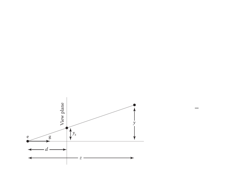
The key property of perspective is that the size of an object on
the screen is proportional to 1/z for an eye at the origin
looking up the negative z-axis.
2D Example:
ꢢ
ꢄꢅ = ꢙ ꢄ
•
•
ꢄ is the distance of the point
along the y-axis.
ꢄꢅ is where the point should
be drawn on the screen.
Perspective Projection
•
In order to implement perspective projection as a matrix
multiplication (in which one of the coordinates of the input
vector appears in the denominator), we can rely on a
generalization of the homogeneous coordinates:
–
In homogeneous coordinates, we represent the point ꢁ, ꢄ, ꢙ as
[ꢁ, ꢄ, ꢙ, 1], where the extra coordinate w is always equal to 1.
–
Rather than just thinking of the 1 as an extra piece in the matrix
multiplication to implement translation, we now define it to be the
denominator of the x-, y-, and z-coordinates:
ꢁ ꢄ ꢙ
, ꢄ, ꢙ, ꢚ → , ,
ꢚ ꢚ ꢚ
ꢁ
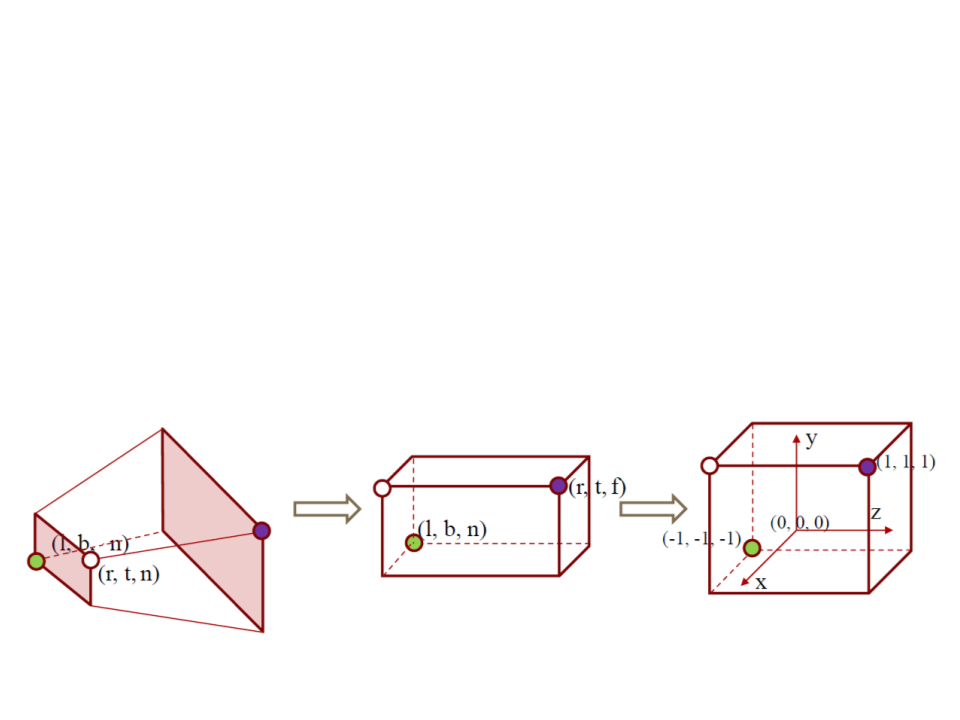
Perspective Projection
•
The perspective matrix maps the Perspective View Volume
(
View Volume (which is an axis-aligned box).
which is shaped like a frustum or pyramid) to the Orthographic
ꢊ 0
0
0
ꢊ + ꢘ −ꢘꢊ
0
0
0
0
0
ꢊ
0
0
ꢣ =
1
0
ꢐꢒꢈꢇ = ꢐꢎꢇꢓℎꢣ
2
ꢊ
ꢕ + ꢔ
0
0
0
ꢔ − ꢕ
ꢕ − ꢔ
ꢗ + ꢖ
2
ꢊ
0
0
ꢐꢒꢈꢇ =
ꢖ − ꢗ ꢗ − ꢖ
ꢘ + ꢊ 2ꢘꢊ
0
ꢊ − ꢘ ꢘ − ꢊ
0
0
1
0
View Volumes
Perspective Projection
•
To integrate the perspective matrix into our implementation,
we simply replace ꢐꢎꢇꢓℎ with ꢐꢒꢈꢇ, which inserts the perspective
matrix P after the camera matrix ꢐꢆꢍꢡ has been applied:
ꢐ = ꢐꢑꢒꢐꢎꢇꢓℎꢣꢐꢆꢍꢡ

Perspective Projection
•
•
To integrate the perspective matrix into our implementation,
we simply replace ꢐꢎꢇꢓℎ with ꢐꢒꢈꢇ, which inserts the perspective
matrix P after the camera matrix ꢐꢆꢍꢡ has been applied:
ꢐ = ꢐꢑꢒꢐꢎꢇꢓℎꢣꢐꢆꢍꢡ
The resulting algorithm is:
construct Mvp
construct Mper
construct Mcam
M = MvpMperMcam
for each line segment (ai, bi) do
p = Mai
q = Mbi
drawline(xp/wp, yp/wp, xq/wq, yq/wq)

...
Matrix4x4 mper = new Matrix4x4();
mper.SetRow(0, new Vector4(near_plane, 0f, 0f, 0f));
mper.SetRow(1, new Vector4(0f, near_plane, 0f, 0f));
mper.SetRow(2, new Vector4(0f, 0f, near_plane + far_plane,
-(far_plane * near_plane)));
mper.SetRow(3, new Vector4(0f, 0f, 1f, 0f));
...
Matrix4x4 m = mvp * ((morth * mper) * mcam);
for (int i = 0; i < world.lines.Length; i+=2)
{
Vector4 p = multiplyPoint(m,
new Vector4(world.vertices[world.lines[i]].x,
world.vertices[world.lines[i]].y,
world.vertices[world.lines[i]].z, 1));
Vector4 q = multiplyPoint(m,
new Vector4(world.vertices[world.lines[i + 1]].x,
world.vertices[world.lines[i + 1]].y,
world.vertices[world.lines[i + 1]].z, 1));
DrawLine(frameBuffer, (int)(p.x / p.w), (int)(p.y / p.w),
(int)(q.x / q.w), (int)(q.y / q.w), Color.white);
}
...
Exercise 2
2
) The implementation of the Perspective Projection is creating
ꢐꢒꢈꢇ by multiplying ꢐꢎꢇꢓℎ and ꢣ, which is not the most
efficient way of performing the perspective projection.
Change the code in order to use the final product of the
matrices:
2
ꢊ
ꢕ + ꢔ
0
0
0
ꢔ − ꢕ
ꢕ − ꢔ
ꢗ + ꢖ
2
ꢊ
0
0
ꢐꢒꢈꢇ = ꢐꢎꢇꢓℎꢣ =
ꢖ − ꢗ ꢗ − ꢖ
ꢘ + ꢊ 2ꢘꢊ
0
ꢊ − ꢘ ꢘ − ꢊ
0
0
1
0
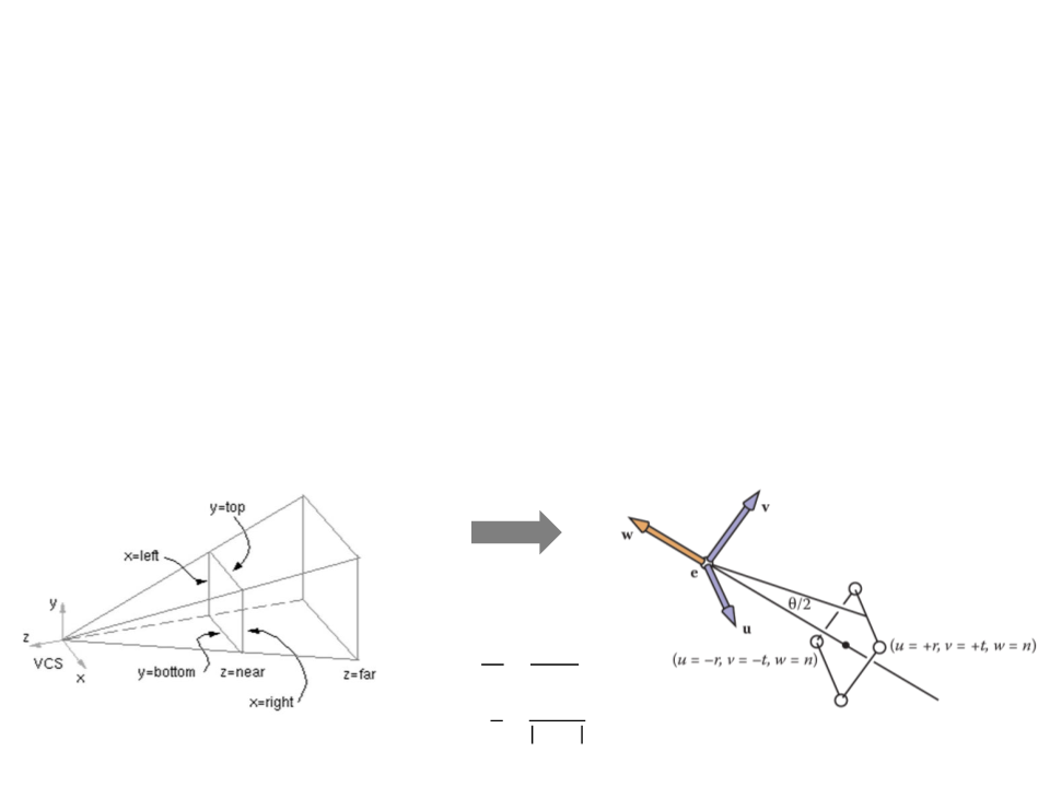
Field-of-View
•
•
As the orthographic view volume, the perspective view volume
can be defined by 6 parameters, in camera coordinates:
–
Left, right, top, bottom, near, far.
However, sometimes we would like to have a simpler system
where we look through the center of the window.
ꢔꢤꢛꢥꢖ = −ꢕꢦꢘꢖ
ꢗꢧꢖꢖꢧꢊ = −ꢖꢧꢨ
ꢊꢋ ꢔꢤꢛꢥꢖ
=
ꢊꢌ
ꢖꢧꢨ
ꢖꢧꢨ
ꢪ
ꢖꢩꢊ =
2
ꢊꢦꢩꢔ
Field-of-View
•
With the simplified system, we have only 4 parameters:
–
–
–
Field-of-view (ꢪ);
Image aspect ratio (screen width/height);
Near, and far clipping planes;
1
0
0
0
0
tan ꢪ ∗ ꢩꢫꢨꢦꢬꢖ
1
tan(ꢪ)
0
0
0
0
ꢐꢒꢈꢇ =
ꢘ + ꢊ 2ꢘꢊ
ꢊ − ꢘ ꢘ − ꢊ
0
0
1
0
Exercise 3
3
) Implement the simplified perspective view volume with field-
of-view in Unity.
–
ꢪ must be converted to radians.
1
0
0
0
0
0
tan ꢪ ∗ ꢩꢫꢨꢦꢬꢖ
1
tan(ꢪ)
0
0
ꢐꢒꢈꢇ =
ꢘ + ꢊ 2ꢘꢊ
ꢊ − ꢘ ꢘ − ꢊ
1
0
0
0
0
Further Reading
•
Hughes, J. F., et al. (2013). Computer Graphics: Principles and Practice
(
0
3rd ed.). Upper Saddle River, NJ: Addison-Wesley Professional. ISBN: 978-
-321-39952-6.
–
Chapter 13: Camera Specifications and Transformations
•
Marschner, S., et al. (2015). Fundamentals of Computer Graphics (4th
ed.). A K Peters/CRC Press. ISBN: 978-1482229394.
–
Chapter 8: Viewing