
Computer Graphics
Lecture 02 – Graphics Pipeline
Edirlei Soares de Lima
<edirlei.lima@universidadeeuropeia.pt>
What is the graphics pipeline?
•
•
The Graphics Pipeline is a special software/hardware
subsystem that efficiently draws 3D primitives on screen.
–
Is optimized for processing 3D triangles with shared vertices.
The basic operations in the pipeline map the 3D vertex
locations to 2D screen positions and shade the triangles so
that they both look realistic and appear in proper back-to-
front order.
–
Geometric manipulation using matrices and vectors.
•
The speed at which images can be generated depends
strongly on the number of triangles being drawn.
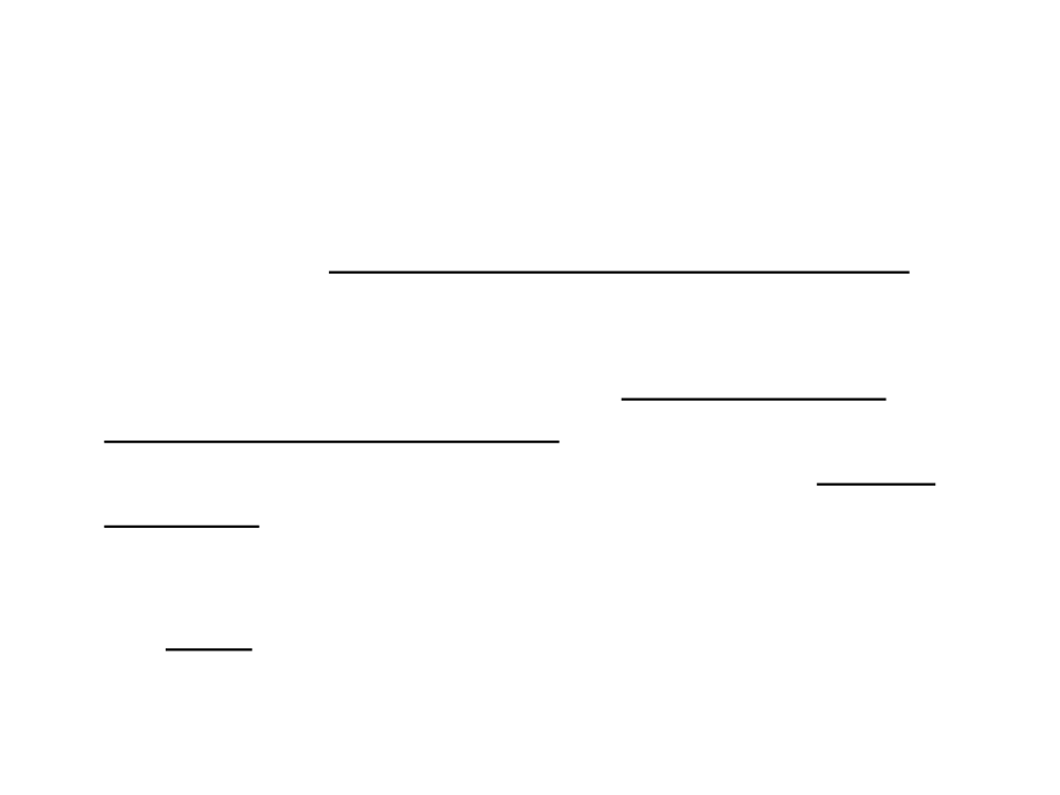
Computer Graphics
Geometric Modeling
Data
Rendering and
Animation
Computer Vision
Image
Image Processing
Rendering
•
One of the basic tasks of computer graphics is rendering
three-dimensional objects.
–
Taking a scene, or model, composed of many geometric objects
arranged in 3D space and producing a 2D image that shows the
objects as viewed from a particular viewpoint.
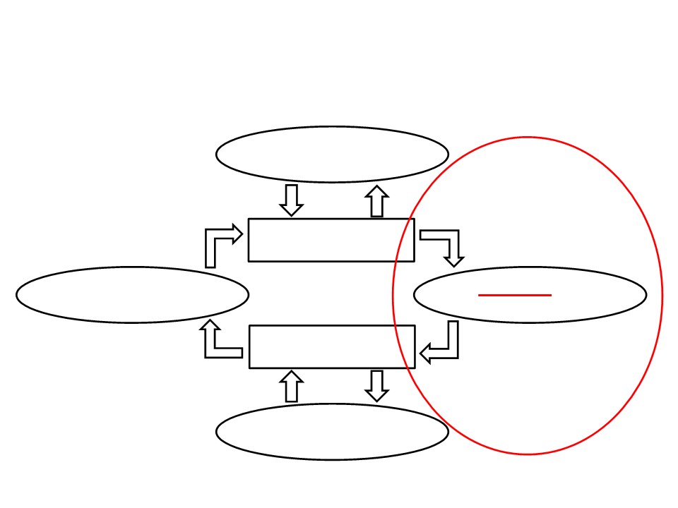
Rendering
Process
3
D Objects
2D Image
•
Rendering involves considering how each object contributes
to each pixel.

Rendering
•
Rendering can be performed in two general ways:
–
Image-order rendering: each pixel is considered in turn, and for each
pixel all the objects that influence it are found and the pixel value is
computed.
for each pixel do
for each object do
...
–
Object-order rendering: each object is considered in turn, and for each
object all the pixels that it influences are found and updated.
for each object do
for each pixel do
...
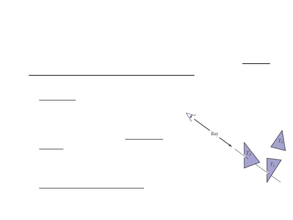
Ray-Tracing
•
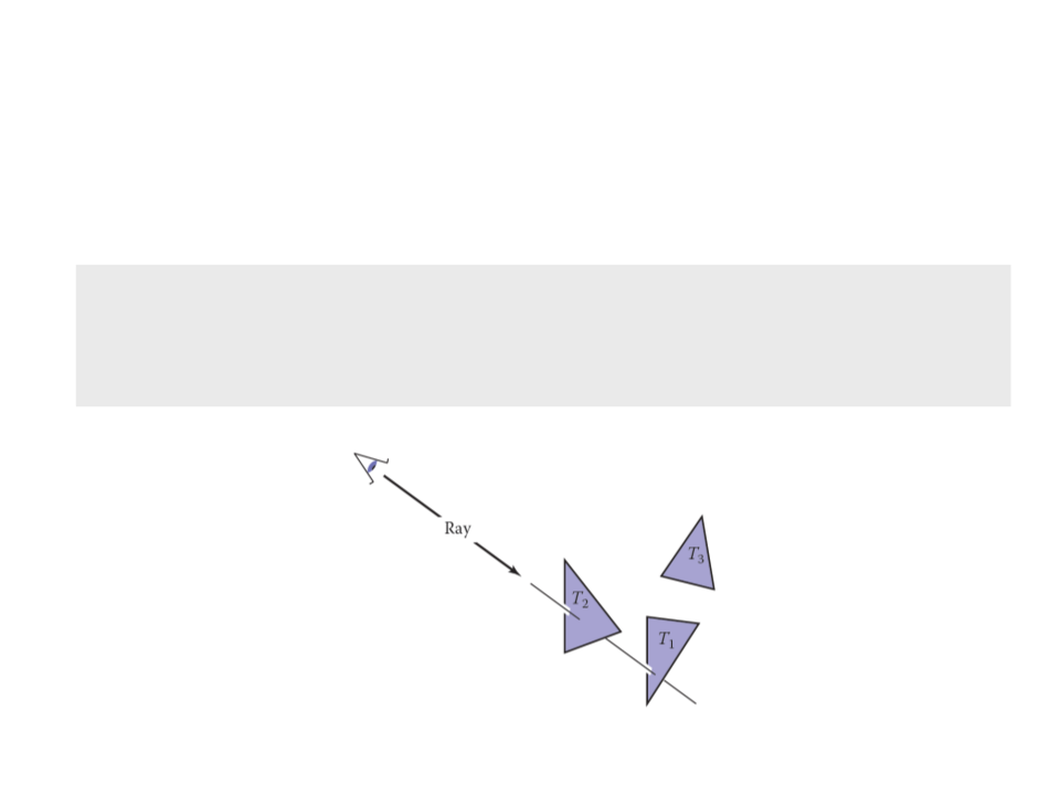
Ray tracing is an image-order algorithm that works by finding
the object that is seen at a pixel’s position in the image.
o An object is seen by a pixel if it intersects the
viewing ray, which is a line that emanates
from the viewpoint in the direction that
pixel is “looking”.
o The object we want is the one that
intersects the viewing ray nearest the
camera.
o Once the object is found, a shading
computation uses the intersection point,
surface normal, and other information to
determine the color of the pixel.
Ray-Tracing
•
The structure of the basic ray tracing algorithm is:
for each pixel do
compute viewing ray
find first object hit by ray and its surface normal n
set pixel color to value computed from hit point,light,and n
Projection
•
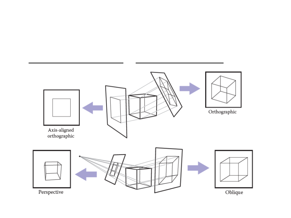
Orthographic Projection vs Perspective Projection
Ray-Tracing – Projection
•
Orthographic Projection vs Perspective Projection
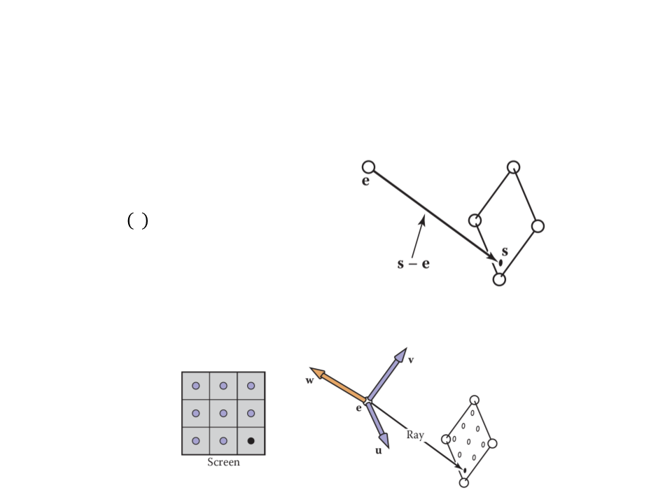
Ray-Tracing – Computing Viewing Rays
•
A ray is defined by an origin point and a propagation direction:
ꢀ
ꢁ = ꢂ + ꢁ(ꢃ − ꢂ)
•
The camera is defined by e (the eye point), and u, v, and w for
the three ba
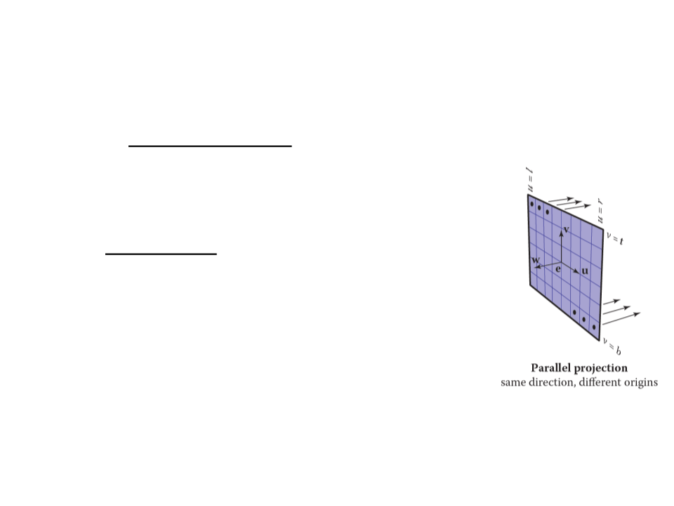
Ray-Tracing – Computing Viewing Rays
•
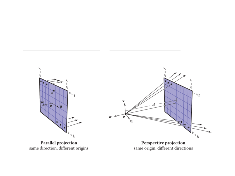
For an orthographic view, all the rays will have
the direction -w and should start on the plane
defined by the point e and the vectors u and v.
•
•
The image plane is defined by the four sides of
the image: l (left), r (right), t (top), b (bottom).
–
l < 0 < r and b < 0 < t.
The pixel at position (i, j) in the raster image is
defined by:
ꢄ = ꢅ + (ꢆ − ꢅ)(ꢇ + 0.5)/ꢈꢉ
ꢆꢎꢏꢓꢒꢑ = −ꢔ
ꢆꢎꢏꢐꢑꢒ = ꢂ + ꢄu + ꢊv
ꢊ = ꢋ + (ꢁ − ꢋ)(ꢌ + 0.5)/ꢈꢍ
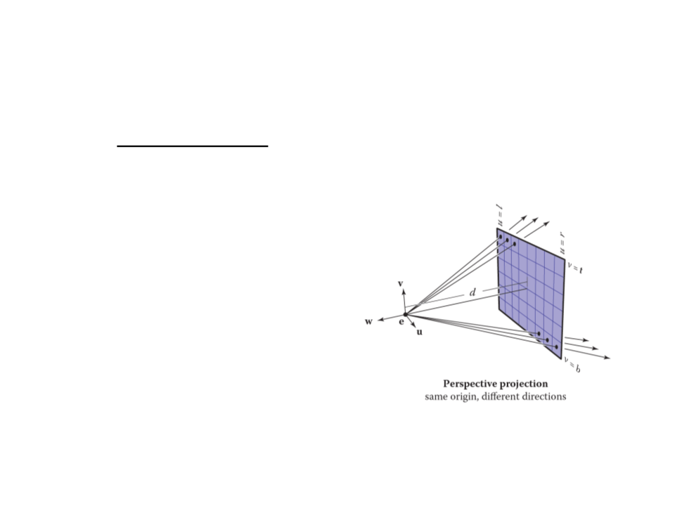
Ray-Tracing – Computing Viewing Rays
•
For a perspective view, all the rays have the same origin, but
their directions are different for each pixel:
ꢆꢎꢏꢓꢒꢑ = −ꢕw + ꢄu + ꢊv
ꢆꢎꢏꢐꢑꢒ = ꢂ

Ray-Tracing – Ray-Object Intersection
•
Ray-Triangle Intersection: Möller–Trumbore algorithm
bool Ray-Triangle(Vector3 rayOrigin, Vector3 rayDir,
Triangle* inTriangle, Vector3& outIntersect){
const float EPSILON = 0.0000001;
Vector3 vertex0 = inTriangle->vertex0;
Vector3 vertex1 = inTriangle->vertex1;
Vector3 vertex2 = inTriangle->vertex2;
Vector3 edge1 = vertex1 - vertex0;
Vector3 edge2 = vertex2 - vertex0;
Vector3 h = rayDir.crossProduct(edge2);
float a = edge1.dotProduct(h);
if (a > -EPSILON && a < EPSILON)
return false;
float f = 1/a;
Vector3 s = rayOrigin - vertex0;
float u = f * (s.dotProduct(h));
if (u < 0.0 || u > 1.0)
return false;
...

Ray-Tracing – Ray-Object Intersection
•
Ray-Triangle Intersection: Möller–Trumbore algorithm
...
Vectort3 q = s.crossProduct(edge1);
float v = f * rayVector.dotProduct(q);
if (v < 0.0 || u + v > 1.0)
return false;
float t = f * edge2.dotProduct(q);
if (t > EPSILON) // ray intersection
{
outIntersect = rayOrigin + rayDir * t;
return true;
}
else
return false;
}

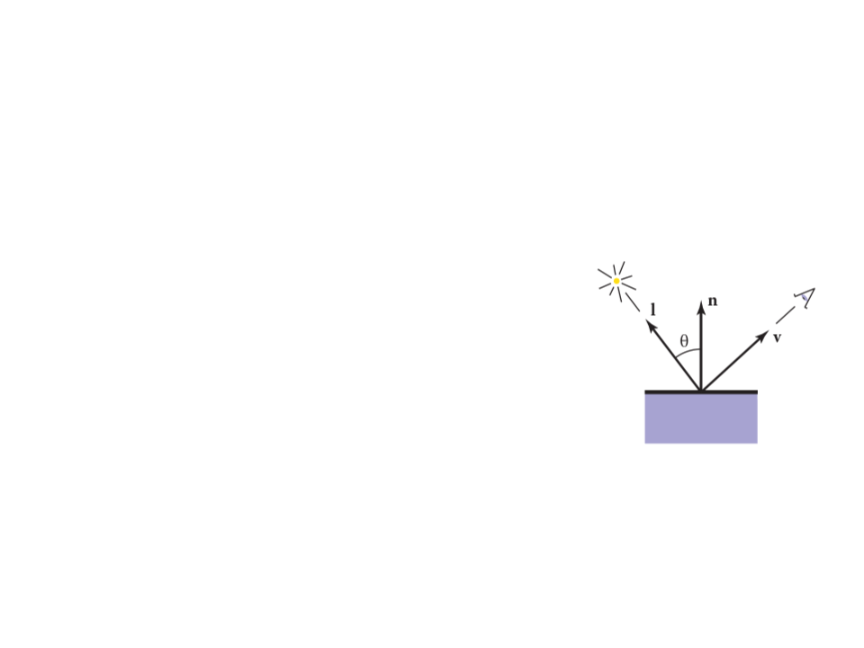
Ray-Tracing – Shading
•
•
Once the visible surface for a pixel is known, the pixel value is
computed by evaluating a shading model.
–
Most shading models are designed to capture the process of light
reflection, whereby surfaces are illuminated by light sources and
reflect part of the light to the camera.
Important variables:
–
–
–
–
Light direction l;
View direction v;
Surface normal n;
Surface characteristics: color, shininess, etc.
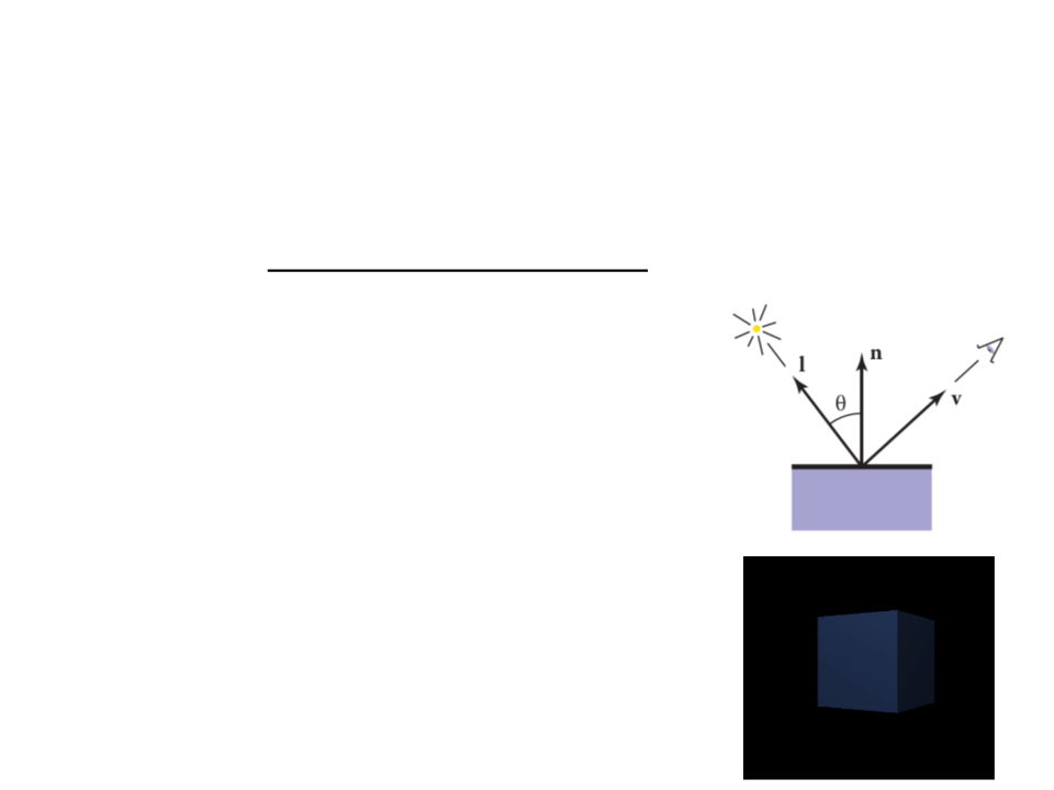
Ray-Tracing – Shading
•
•
Lambertian Shading: the amount of energy from a light source
that falls on an area of the surface depends on the angle of the
surface to the light.
ꢖ = ꢗꢓꢘꢙꢎꢚ(0, ꢈ ∙ ꢅ)
where:
–
–
–
–
ꢖ is the pixel color;
ꢗꢓ is the diffuse coefficient, or the surface color;
ꢘ is the intensity of the light source;
ꢈ ∙ ꢅ = cos θ

Ray-Tracing Program
for each pixel do
compute viewing ray
if (ray hits an object with t ∈ [0,∞)) then
Compute n
Evaluate shading model and set pixel to that color
else
Set pixel color to background color
•
Other ray-tracing topics:
–
–
–
–
Shadows;
Reflections;
Transparency and Refraction;
Parallel ray-tracing;

Ray-Tracing – Unity Implementation
public class RayTracer : MonoBehaviour {
private Texture2D renderTexture;
private int l = -1;
private int r = 1;
private int b = -1;
private int t = 1;
void Start ()
{
renderTexture = new Texture2D(Screen.width, Screen.height);
}
void OnGUI()
{
GUI.DrawTexture(new Rect(0, 0, Screen.width, Screen.height),
renderTexture);
}
...

Ray-Tracing – Unity Implementation
...
void RayTrace()
{
for (int x = 0; x < renderTexture.width; x++)
{
for (int y = 0; y < renderTexture.height; y++)
{
float u = l + ((r - l) * (x + 0.5f)) / Screen.width;
float v = b + ((t - b) * (y + 0.5f)) / Screen.height;
Ray ray = new Ray(new Vector3(u, v, 0), transform.forward);
renderTexture.SetPixel(x, y, TraceRay(ray));
}
}
renderTexture.Apply();
}
...

Ray-Tracing – Unity Implementation
...
Color TraceRay(Ray ray)
{
RaycastHit hit;
if (Physics.Raycast(ray, out hit))
{
Material mat = hit.collider.gameObject.GetComponent
<Renderer>().material;
return mat.color;
}
return Color.black;
}
void Update()
{
RayTrace();
}
}

Ray-Tracing – Unity Implementation
•
For a perspective view, we can use the ScreenPointToRay
function to compute the ray:
void RayTrace()
{
for (int x = 0; x < renderTexture.width; x++)
{
for (int y = 0; y < renderTexture.height; y++)
{
Ray ray = GetComponent<Camera>().ScreenPointToRay(
new Vector3(x, y, 0));
renderTexture.SetPixel(x, y, TraceRay(ray));
}
}
renderTexture.Apply();
}
Exercise 1
1
) Change the implementation of the Unity raytracing program
to use the Lambertian shading model to determine the color
of the rendered object.
–
Remember that in the Lambertian model
the pixel color is determined by:
ꢖ = ꢗꢓꢘꢙꢎꢚ(0, ꢈ ∙ ꢅ)
–
Hint 1: first you need to define the position
of a light source.
–
Hint 2: the equation is applied separately to
the three color channels.

Ray-Tracing
•
•
Ray tracing was developed early in the history of computer
graphics, but was not used until sufficient compute power
was available.
–
Although it was traditionally thought of as an offline method, real-
time ray tracing implementations are becoming more and more
common.
It has a worst asymptotic time complexity than basic object-
order rendering.

Rendering
•
•
The alternative to the image-order rendering, is the object-
ordered rendering, where each object is considered in turn,
and for each object all the pixels that it influences are found
and updated:
for each object do
for each pixel do
...
Object-order rendering has enjoyed great success because of
its efficiency.
–
For large scenes, a single pass over the scene has significant
advantages over repeatedly searching the scene to retrieve the
objects required to shade each pixel.
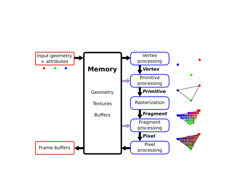
Graphics Pipeline
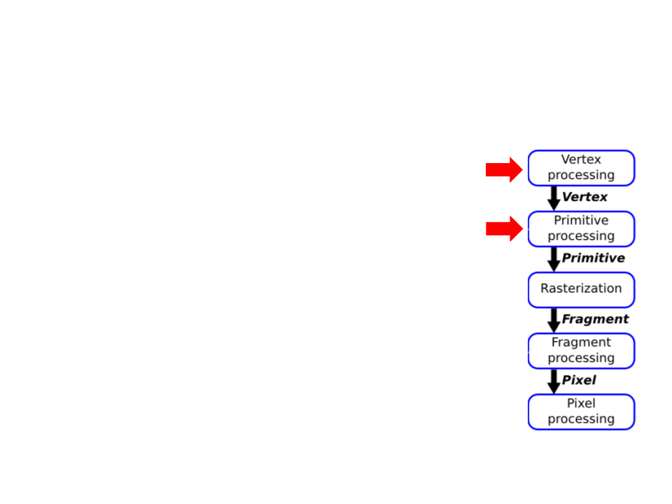
Graphics Pipeline
•
Vertex Processing and Primitive Processing:
–
–
–
–
–
Input: vertex and attributes;
Vertex Assembly;
Modeling, Viewing, and Projection Transformations;
Clipping;
Backface Culling;
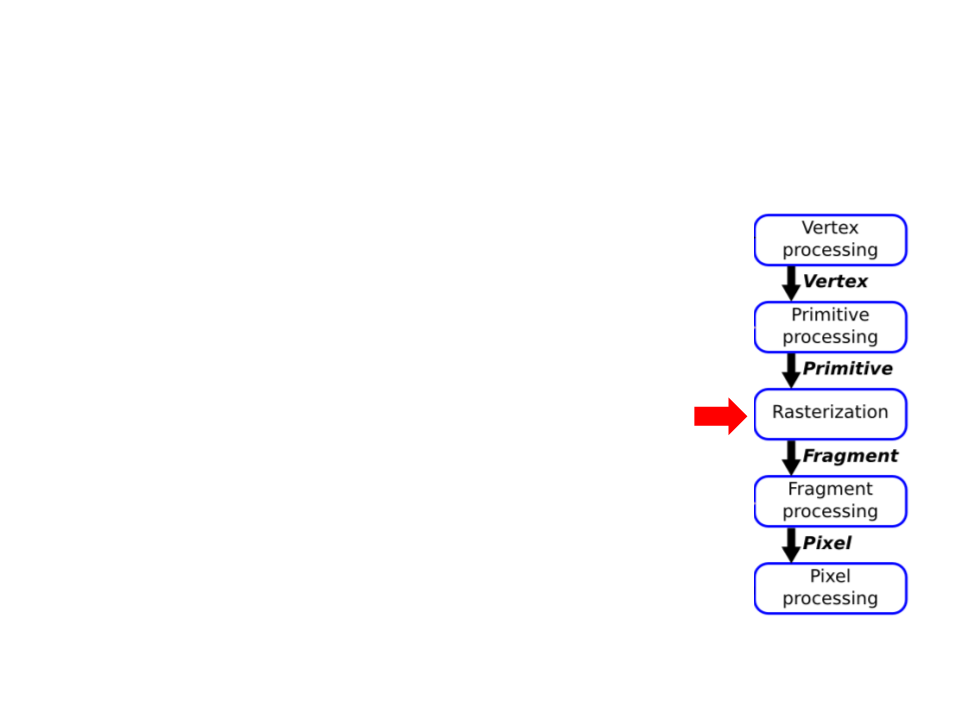
Graphics Pipeline
•
Rasterization:
–
–
–
Fragment generation;
Multiple possible fragments per pixel;
Interpolation attributes along each primitive;
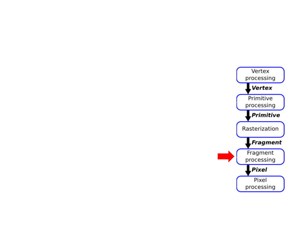
Graphics Pipeline
•
Fragment Processing:
–
–
–
–
–
Compute color of each fragment;
Compute depth of each fragment;
Per-fragment Shading;
Texture Mapping;
Remove hidden surfaces (z-buffer algorithm);
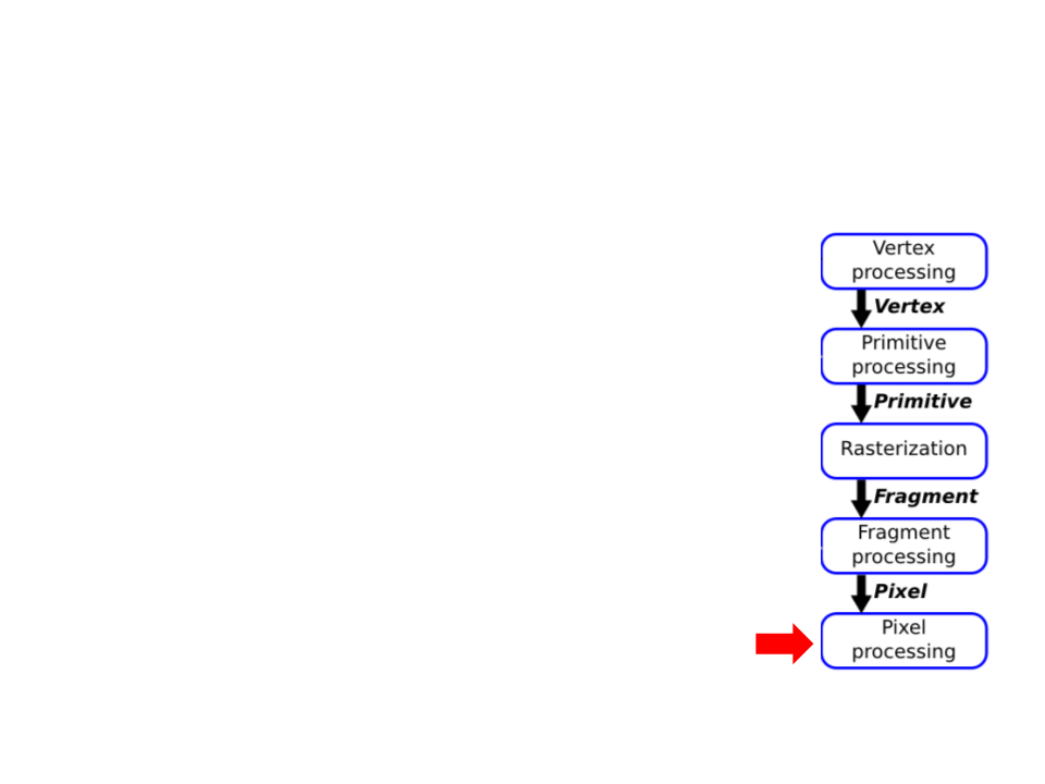
Graphics Pipeline
•
Pixel Processing:
–
The various fragments corresponding to each pixel
are combined;
–
Write the output image in the frame buffer;
Graphics Pipeline – Example
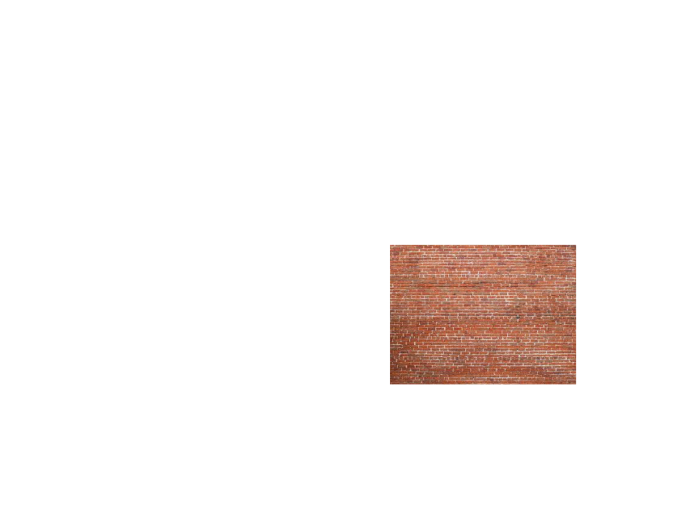
•
Input:
–
–
vertices = {v0x, v0y, v0z,
v1x, v1y, v1x,
v2x, v2y, v2z,
v3x, v3y, v3x,
v4x, v4y, v4z,
Texture map
v5x, v5y, v5x}
texture_coords = {v0u, v0v,
v1u, v1v,
v2u, v2v,
v3u, v3v,
v4u, v4v,
v5u, v5v}
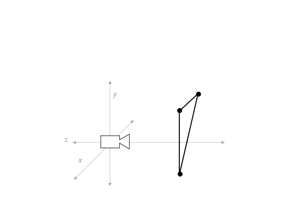
Graphics Pipeline – Example
•
Step 1: Transform triangle vertices into camera space.
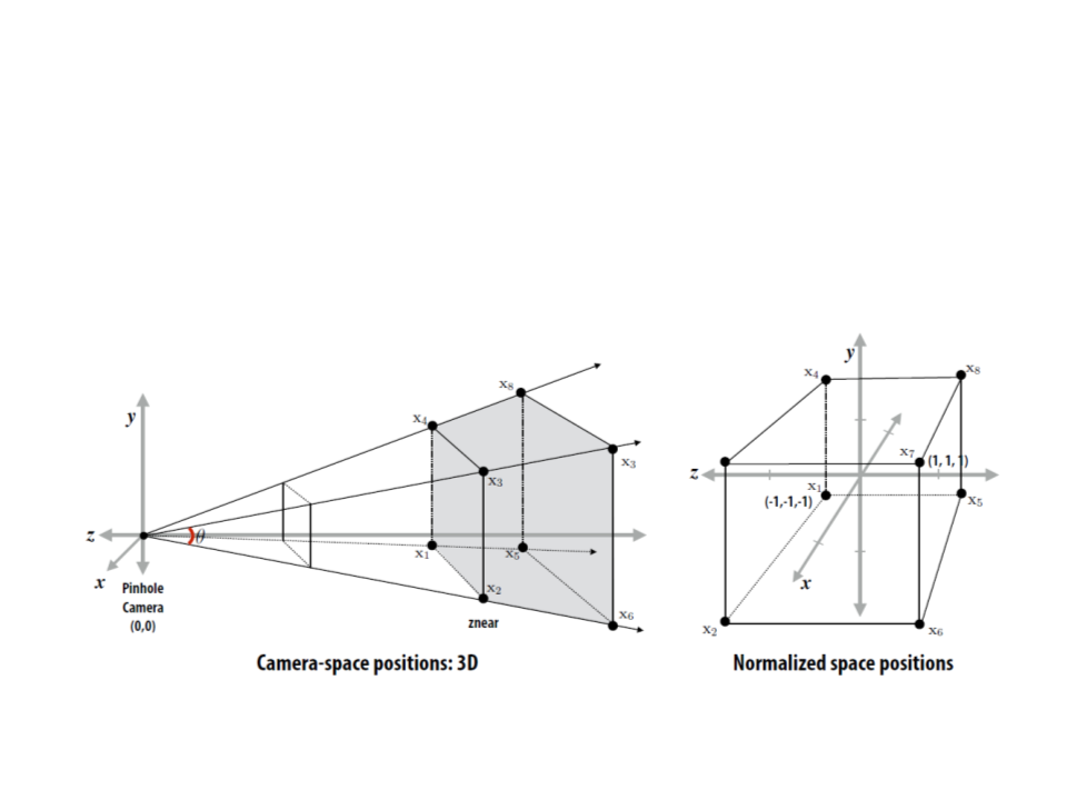
Graphics Pipeline – Example
•
Step 2: Apply perspective projection to transform triangle
vertices into a normalized coordinate space (canonical view
volume).
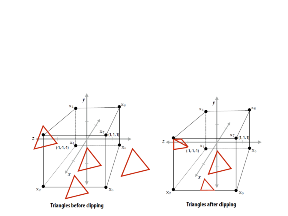
Graphics Pipeline – Example
•
Step 3: Discard triangles that lie complete outside the
canonical view volume and clip triangles that extend beyond
the canonical view volume (possibly generating new triangles).
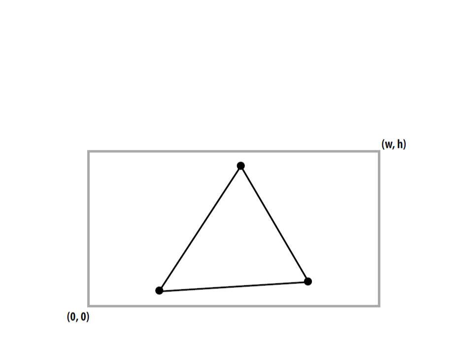
Graphics Pipeline – Example
•
Step 4: Transform vertex positions from the canonical view
volume into screen coordinates (x, y).
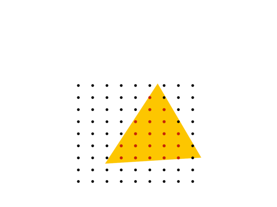
Graphics Pipeline – Example
•
Step 5: break each primitive into a number of fragments, one
for each pixel covered by the primitive.
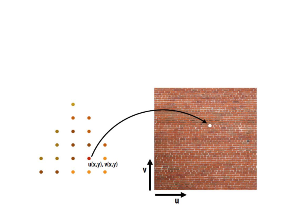
Graphics Pipeline – Example
•
Step 6: perform a texture mapping or other more advanced
shading computation per fragment.
Graphics Pipeline – Example
•
Step 7: compute the depth of each fragment (z-buffer
algorithm).
Graphics Pipeline – Example
•
Step 8: update the frame buffer.
Graphics Pipeline
•
The graphics pipeline is simply a way to describe the
functioning of a standard graphics system.
–
The exact implementation of the graphics pipeline or even the order
in which the tasks are performed may vary.
•
•
The pipeline can be seen as a black box, but some
understanding of the nature of the processing is valuable.
Currently, the fixed-function pipeline model is being
replaced by shaders.
–
However, the fixed-function pipeline makes a good conceptual
framework where we can add variations, which is how most shaders
are in fact created.
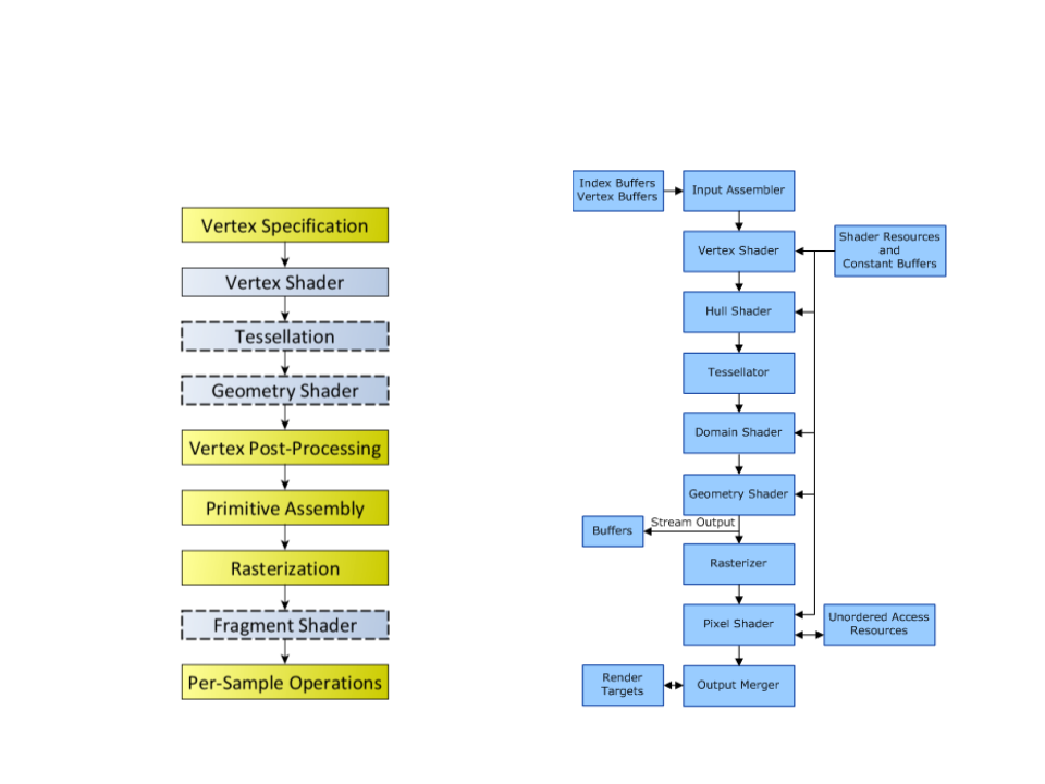
OpenGL vs Direct3D
OpenGL
Direct3D

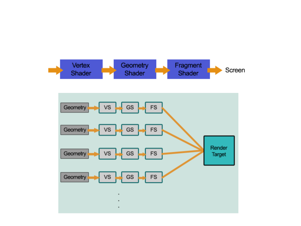
Unity Rendering Pipeline
•
Unity supports two main rendering paths:
–
Forward Rendering: renders each object in one or more passes,
depending on lights that affect the object.
•
Is based on the traditional linear graphics pipeline, where each geometry is
processed by the pipeline (one at a time) to produce the final image.
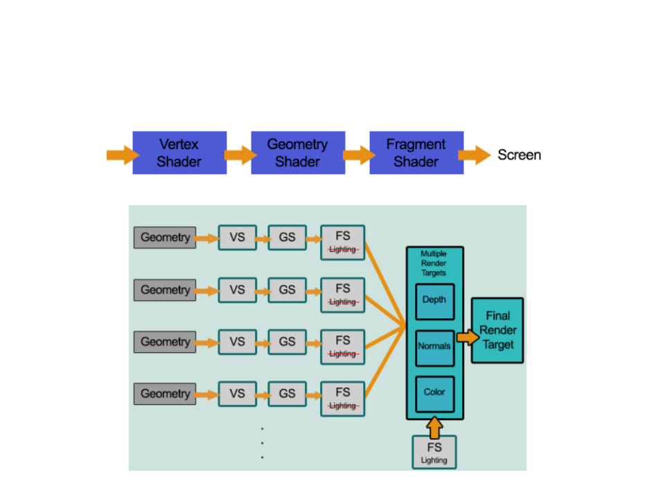
–
Deferred Rendering: renders each object once on the first pass and
stores shading information into G-buffer textures. Additional passes
compute lighting based on G-buffer and depth in screen space.
•
The rendering is "deferred" until all of the geometries have been processed by the
pipeline. The final image is produced by applying shading/lightning at the end.
Forward Rendering
Deferred Rendering

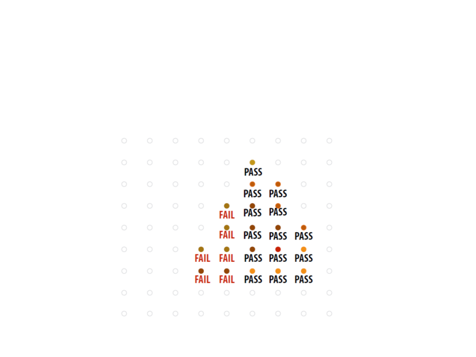
Forward vs. Deferred
•
Deferred rendering is better for lighting:
–
In a standard forward rendering pipeline, the lighting calculations have
to be performed on every vertex and on every fragment in the visible
scene, for every light in the scene.
•
•
Complexity:
–
Forward: O(number_of_fragments * number_of_lights)
–
Deferred: O(number_of_pixels * number_of_lights)
Deferred rendering problems:
–
–
–
No support for anti-aliasing;
No support for semi-transparent objects;
Not supported by old video cards and mobile devices.

Further Reading
•
Hughes, J. F., et al. (2013). Computer Graphics: Principles and Practice
(
0
3rd ed.). Upper Saddle River, NJ: Addison-Wesley Professional. ISBN: 978-
-321-39952-6.
–
Chapter 1: Introduction
–
Chapter 15: Ray Casting and Rasterization
•
Marschner, S., et al. (2015). Fundamentals of Computer Graphics (4th
ed.). A K Peters/CRC Press. ISBN: 978-1482229394.
–
–
–
Chapter 4: Ray Tracing
Chapter 8: The Graphics Pipeline
Chapter 13: More Ray Tracing